Disarray “Recharged” - Is Blue LED Supposed to Light Up?

Caldo71

Active member
Hey so I just finished this build and it sounds KILLER: really, really happy with how this sounds. Top switch positions sounds perhaps a bit more “compressed and modern” albuit quieter with a smooth top end, middle position much like an Agry Charles with (lots) more gain on tap.

That said, bottom switch position sounds identical to the middle position to my ears, and the blue LED does not light up in any if the three switch positions. Is it SUPPOSED to, or does it work in the curcuit in some other way I don’t understand?

And before you ask, yes: I did check to make absolutely sure the cathode was wired to the proper pad.

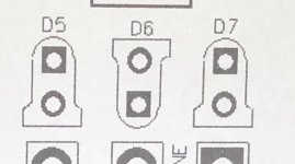
To add to my confusion, the pcb has the cathodes all facing the same way (see photo below) while the layout in the instructions (also below) shows them alternating. And when I play through the pedal, the red LEDs flicker satisfyingly in the middle position but not in the others. But all positions seem to SOUND good?!?!
71579FC7-7E9F-4BE8-A9AA-001F99E2E359.jpeg F40580B4-BB0D-4A11-B43B-ECCCB7BC347B.jpeg
 
D5 is Cathode to ground. D6 & D7 are anode to ground.
Hey @fig just to make sure: this is definitely true of the NEWEST iteration of this PCB? I only ask because of what is seen in my two photos where the pcb itself shows all cathodes facing the same direction, whilst by contrast, the downloadable build instructions match the older versions of the PCB that show alternating cathode alignment.
Thanks!
 
Follow the silkscreen printing on your PCB for the diode orientation. If the Red LEDs light up in any position you have them oriented correctly.

This sounds like an issue with the toggle switch, where did you get your switch (and what part number)?
 
  • Like
Reactions: fig
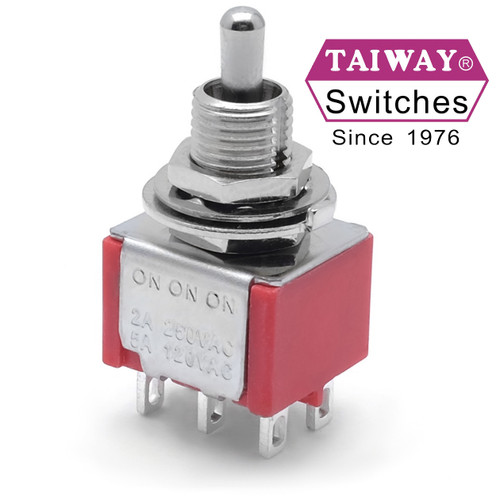
Well, @PedalPCB, regarding the toggle, this is actually the second time I’ve been through the on-on-on switch issue on this forum. See this thread...
https://forum.pedalpcb.com/threads/can-someone-demystify-“type-1”-versus-“type-2”-dpdt-switches-for-me.5385/#post-44619

...and as a result of
@music6000 ’s recommend, I went with THIS little guy...

so I feel like I should be solid with that...you tell me.

Anyhow, to address your other comments, the LEDs are indeed wired as-per the silkscreening, and in the middle position, both red LEDs absolutely light up (and sound great).
 
I was referencing the current schematic. Whether or not they align physically is not necessarily indicative of their orientation in the circuit. Anyway, you have the source - @PedalPCB on the case, and I hope you get it sorted!
 
I was referencing the current schematic. Whether or not they align physically is not necessarily indicative of their orientation in the circuit. Anyway, you have the source - @PedalPCB on the case, and I hope you get it sorted!
I see what you mean now!

But yeah if @PedalPCB can confirm that the three-way on/on/on switch I purchased is the right kind, I'm not sure what's next other than just de-soldering/re-soldering another switch to make sure it's not a bad part or bad soldering.

Regardless it sounds killer, but you know it's nice to have the satisfaction of an 100% functional build including all optional tones.
 
  • Like
Reactions: fig
That said, bottom switch position sounds identical to the middle position to my ears
I find the up and down positions to sound very similar on my build. The middle is noticeably different than the other two (less compressed).

I see the red leds light up (quite brightly) when I play and my switch is in the up position. I don't see the blue led light up any in position.
 
That should be the correct switch, but something isn't quite right.

The red LEDs should only be active when the switch is up. They should be out of circuit in the middle and lower positions.

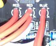
If you wired the toggle switch offboard I'd definitely double check the wiring.
 
That should be the correct switch, but something isn't quite right.

The red LEDs should only be active when the switch is up. They should be out of circuit in the middle and lower positions.

If you wired the toggle switch offboard I'd definitely double check the wiring.
Yeah I was wondering that myself—you are correct about the offboard thing. That is allowing me to mount this sucker in a 2RU housing with other pedals which you’ve probably devined from my other build posts.

But the six little cable extendo wires are definitely “apples-to-apples”...no crossed wires here.

So I may have stated earlier that on mine only the middle position lights up the red LEDs? That was incorrect: both middle and bottom positions light up the red LEDs and those sound completely identical. Louder, more “raw”, sloppier bottom end, nicer sounding at low gain settings.

The top position is a little quieter, more “modern” with a tight bottom, less low end, compressed, KILLER hi-gain tones, but sounds less honest and full range at lower gains.

So it seems like maybe the bottom position is the one where the 3-way switch is failing to “choose” the blue LED and second pair of small diodes?
 
Last edited:
@PedalPCB Looking at the Disarray schematic, it looks like the blue LED is oriented in the same direction as the two zeners. Wouldn't this only clip the signal in one direction (and prevent the LED from lighting)? Compared to the Aion version, they've got the zeners oriented opposite the LED, which is what I'd expect.

Is this an error with the schematic or intended? Is the board wired the same way?
 
Hmm.. this has been mentioned before, and I want to say it was reverified in the original..... but now I can't find any trace of the thread. It must have been before the big forum crash of '19.

It does make more sense with the blue LED oriented the opposite direction. I'm going to have to see if I still have the original around here...

(Regardless, this would have nothing to do with the OPs issue of the red LEDs lighting in the wrong switch position)
 
  • Like
Reactions: fig
Back
Top