Dream Fuzz not working…

timsamoff

New member
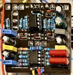
49A86BD0-2857-4F6D-816B-DDFC1D26E4DD.jpeg Hi all,

I realize that this may be tough to troubleshoot in this way, but I just can’t figure out what’s wrong. I’ve done a fault trace and an audio probe and I can’t find where the breakdown is.

When the pedal is in bypass, the sound is really low, even though the 3PDT switch tests out just fine. When the pedal is on, it’s just buzzes like there’sa serious ground issue.

All of the pots and the toggle switch test fine as well.

I’m not counting out some sort of assembly issue — this is my first kit — and I did swap out a couple of caps for what I had on hand.

Does this look ok on a surface level? Sorry, I’m a bit of a n00b with this.

Thanks!
Tim
 
View attachment 19052Hi all,

I realize that this may be tough to troubleshoot in this way, but I just can’t figure out what’s wrong. I’ve done a fault trace and an audio probe and I can’t find where the breakdown is.

When the pedal is in bypass, the sound is really low, even though the 3PDT switch tests out just fine. When the pedal is on, it’s just buzzes like there’sa serious ground issue.

All of the pots and the toggle switch test fine as well.

I’m not counting out some sort of assembly issue — this is my first kit — and I did swap out a couple of caps for what I had on hand.

Does this look ok on a surface level? Sorry, I’m a bit of a n00b with this.

Thanks!
Tim

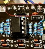
Try reflowing these:

6F86BD96-EC1E-4731-B0EF-8DE32EEC6996.jpeg

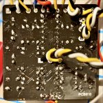
Also, post pictures of the underside of the board as well.
 
Well, I reflowed the solder on those joints (as well as a couple of others) and I swapped out R1 for the correct value. R9 is supposed to be 47ohm, and it is.

To no avail.

I hate giving up, but this seems like a lost cause. I’ve been trying to figure it out for a few weeks now and I think it’s time to move on.

Thanks for the help!

You said you audio probed the circuit? And turned up nothing?

Did that include the path from input to switch and input to board and then output?
 
I went as fast as I could with my limited knowledge. I get signal to the output with it in bypass, of course, but lose track somewhere in between with it on.

I know this isn’t a good answer, but I’m at my wits end. 😓
 
Post pics of your DC jack and in and out jacks so the wiring can be traced

Are you getting 9v to the pcb
That was the first thing I checked — definitely getting 9V to the PCB.

I’ve since disconnected the DC jack from the PCB while testing (I’ve been connecting it with alligator clips).

Anyway, I appreciate the help. I need to step away for a bit. 😁 I’m now working on the Magnetron Delay.
 
Back
Top