MichaelW
Well-known member
- Build Rating
- 5.00 star(s)
So I originally built the Phase II (Mutron Phasor) because @Betty Wont said it was the coolest phasor on the planet, she wasn't wrong!
It's definitely my favorite (But I've only built 2 phasors so that may not be saying much.)
So I figured if ONE was kick ass, then TWO must be Kick Ass-er right?
Holy crap this was a long build (for me).
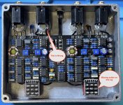
Took me all afternoon. Hardest part was gathering all the components. It's not a difficult build but the sheer volume of components can seem overwhelming. But once you get started it's not too bad. Lots of the same value components. (Like a crap ton of 4k7 resistors) and FIFTEEN ic's holy moly!
Anyway, I got it done....and realized a mistake I made. (I think). I assumed the 4 jack method only needed a TRS stereo jack for the switching jack.
I think I may have been mistaken because I can only get it to work in series (using I/O jacks A) but the B side does not work independently.
Granted I only spent about 10 minutes with it. I have some true switched jacks that I'll swap out tomorrow.
VERY cool having them running in series mode with two different LFO speeds. Right now I have the trimmers set up @Betty Wont style, meaning all set to noon. I think I'm going to need to fiddle with these a bit after fixing the switching jack issue.
I been on a roll with the modulation pedals as of late, the 'Lectric Mama Flanger, the Mini-Me Chorus and the Duo-Phase. On my bench next is going to be my next Muffin variant, the Green Russian. Waiting for the paint to dry on the enclosure
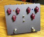
For the Duo-Phase I decided to go with a custom color. So I ordered a 1590xx in bare aluminum on my last Tayda order.
I drilled first, then painted with primer and my new favorite color, the "Burnished Amber" rattle can.
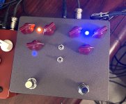
This enclosure came out pretty nice. Now just read some old threads to figure out what these egnimatic toggles do.....and fix the side B jacks.
Best sounding phasor in the world times TWO!!!


It's definitely my favorite (But I've only built 2 phasors so that may not be saying much.)
So I figured if ONE was kick ass, then TWO must be Kick Ass-er right?
Holy crap this was a long build (for me).
Took me all afternoon. Hardest part was gathering all the components. It's not a difficult build but the sheer volume of components can seem overwhelming. But once you get started it's not too bad. Lots of the same value components. (Like a crap ton of 4k7 resistors) and FIFTEEN ic's
Anyway, I got it done....and realized a mistake I made. (I think). I assumed the 4 jack method only needed a TRS stereo jack for the switching jack.
I think I may have been mistaken because I can only get it to work in series (using I/O jacks A) but the B side does not work independently.
Granted I only spent about 10 minutes with it. I have some true switched jacks that I'll swap out tomorrow.
VERY cool having them running in series mode with two different LFO speeds. Right now I have the trimmers set up @Betty Wont style, meaning all set to noon. I think I'm going to need to fiddle with these a bit after fixing the switching jack issue.
I been on a roll with the modulation pedals as of late, the 'Lectric Mama Flanger, the Mini-Me Chorus and the Duo-Phase. On my bench next is going to be my next Muffin variant, the Green Russian. Waiting for the paint to dry on the enclosure
For the Duo-Phase I decided to go with a custom color. So I ordered a 1590xx in bare aluminum on my last Tayda order.
I drilled first, then painted with primer and my new favorite color, the "Burnished Amber" rattle can.
This enclosure came out pretty nice. Now just read some old threads to figure out what these egnimatic toggles do.....and fix the side B jacks.
Best sounding phasor in the world times TWO!!!


Last edited:

