Svenson007
Active member
Hey guys. I’ve built a handful of the duocast pedals…. Never had trouble.
It had been a while, so my memory is foggy.
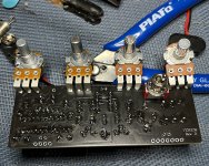
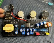
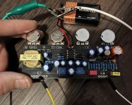
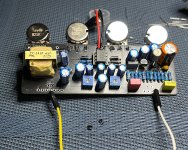
You will see in the pics, to test, I would insert a temporary attachment wire on the forth to left pad (some sort of input) This is attached to my input jack. On the right hand side I wound use the furthest right pad in the same way. As the output. Should I be getting any overdrive effects just from this? Don’t think so with the way it’s wired.
This gives me a clean tone but without control over the pots etc.
I guess I’m asking how you guys “rock it before you box it”
Since it’s been a while I can’t remember if I was satisfied that the clean tone was making it through and then go ahead with the complicated wiring (which I don’t totally know how it functions in the circuit. It’s not something I’m used to, but has worked fine for me in the past.
How can I test the circuit before commitimg to the rest of the build? I guess the fact I was getting signal to pass through, in the past was when I would move in to completing the build. No problems in the past.
But it’s been a long time, and I’m not 100% sure this method is sound.
I feel like if I just complete the build the wiring works it’s way out after getting clean signal during test.
I’m not feeling so confident this time.
If anyone can give me some insight that would be epic. I don’t really understand how each switch interacts.
I’ve made some great duocast pedals in the past. And I think it was just testing for the clean tone and move on. But I’m not convinced, and seems shoddy technique. My memory has crapped out on me.
Would love some insight into this! Would love to get this complete tomorrow. This is the first time doubting myself with this one.
P.s the camera angle makes my solder joints look meh…. But they are quite good in real life. I even reflowed them just in case.
Please help my pedal nerd friends!!!")
Cheers
It had been a while, so my memory is foggy.
You will see in the pics, to test, I would insert a temporary attachment wire on the forth to left pad (some sort of input) This is attached to my input jack. On the right hand side I wound use the furthest right pad in the same way. As the output. Should I be getting any overdrive effects just from this? Don’t think so with the way it’s wired.
This gives me a clean tone but without control over the pots etc.
I guess I’m asking how you guys “rock it before you box it”
Since it’s been a while I can’t remember if I was satisfied that the clean tone was making it through and then go ahead with the complicated wiring (which I don’t totally know how it functions in the circuit. It’s not something I’m used to, but has worked fine for me in the past.
How can I test the circuit before commitimg to the rest of the build? I guess the fact I was getting signal to pass through, in the past was when I would move in to completing the build. No problems in the past.
But it’s been a long time, and I’m not 100% sure this method is sound.
I feel like if I just complete the build the wiring works it’s way out after getting clean signal during test.
I’m not feeling so confident this time.
If anyone can give me some insight that would be epic. I don’t really understand how each switch interacts.
I’ve made some great duocast pedals in the past. And I think it was just testing for the clean tone and move on. But I’m not convinced, and seems shoddy technique. My memory has crapped out on me.
Would love some insight into this! Would love to get this complete tomorrow. This is the first time doubting myself with this one.
P.s the camera angle makes my solder joints look meh…. But they are quite good in real life. I even reflowed them just in case.
Please help my pedal nerd friends!!!
Cheers
Attachments
Last edited: