Chuck D. Bones
Circuit Wizard
The Executive Fuzz and Teddy Rupture are both based on the Jordan Boss Tone. These are all fine pedals, but there is always something we can do to make them a little bit better.
Three mods:
1) More bass
2) More volume, less compression
3) Tone control
These mods can be used individually or in any combination. Ref designators apply to both pedals.
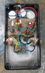
Full disclosure: I built a Teddy on a Vero board because it's a simple circuit and I knew I was going to try various mods. These mods can be implemented on the Executive or Teddy Rupture boards.
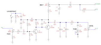
The first mod is about extending the low frequency response. I've read comments on other forums about the lack of bass response on the Jordan Boss Tone and it's certainly true. If you're running humbuckers, then the bass response of the Executive & Teddy might be fine as-is. But if you have single coil pickups, want to play bass thru this pedal, or just have more bottom-end grunt, then you will like this mod. The mod involves changing a capacitor and adding a resistor. Increasing C2 from 22nF to 100nF extends the bass response from 400Hz down to 60Hz. That by itself works fine unless you set the ATTACK (GAIN) control to 0 or 10. At the 2 extreme settings, this mod makes a big gain bump at 45Hz. To tame that, you have to insert a 33K resistor in series with C1. It's easily done by clipping pin 2 on the ATTACK (GAIN) pot, then soldering a 33K resistor between the clipped pin and the pad on the circuit board. On mine, I installed a switch that puts a 100nF cap in parallel with the original 22nF C2 so I can turn the mod on and off. I also installed an optional 3.3Meg anti-pop resistor across the switch.
The second mod replaces the clipping diodes with yellow LEDs. Simple as that. For a little more variety, use a DPDT ON-OFF-ON toggle switch to select between Si diodes, LEDs or no diodes. The LEDs and diodes can be mounted on the switch.
The third mod adds a treble-cut TONE control. Clip pin 3 of the VOLUME pot, insert a 47K resistor between the pot and the pad on the circuitboard. Connect pin 1 of the TONE pot to pin 3 of the VOLUME pot. Solder a 6.8nF capacitor from pin 2 of the TONE pot to the case of the pot. When the TONE pot is mounted in the box, it will ground to the chassis. If you don't trust that method of grounding, run a wire from the TONE pot body to the ground lug on the OUTPUT connector. With a 6.8nF capacitor, the treble cut is fairly mild. You can make the cap bigger, say 10nF or 22nF if you want a darker tone. Pin 3 of the TONE pot is left open. This mod reduces the maximum volume available by 3dB, more if the next pedal in the chain has an input impedance less than 100K. Mod 2 more than makes up for the volume loss.
One last thing, 2N2222A transistors can be noisy. You can replace Q1 in the Executive with any low-noise Si NPN and the only tonal difference will be less noise. Teddy uses a BC109C, which is low-noise. I used 2N5210 because I have a pile of them.
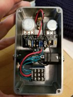
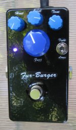
I built mine in a pre-drilled box from Tayda. I added the holes for the violet LED and BASS toggle switch. The toggle and two of the pots mount directly to, and support, the board. The big knob is the FUZZ control.
Three mods:
1) More bass
2) More volume, less compression
3) Tone control
These mods can be used individually or in any combination. Ref designators apply to both pedals.
Full disclosure: I built a Teddy on a Vero board because it's a simple circuit and I knew I was going to try various mods. These mods can be implemented on the Executive or Teddy Rupture boards.
The first mod is about extending the low frequency response. I've read comments on other forums about the lack of bass response on the Jordan Boss Tone and it's certainly true. If you're running humbuckers, then the bass response of the Executive & Teddy might be fine as-is. But if you have single coil pickups, want to play bass thru this pedal, or just have more bottom-end grunt, then you will like this mod. The mod involves changing a capacitor and adding a resistor. Increasing C2 from 22nF to 100nF extends the bass response from 400Hz down to 60Hz. That by itself works fine unless you set the ATTACK (GAIN) control to 0 or 10. At the 2 extreme settings, this mod makes a big gain bump at 45Hz. To tame that, you have to insert a 33K resistor in series with C1. It's easily done by clipping pin 2 on the ATTACK (GAIN) pot, then soldering a 33K resistor between the clipped pin and the pad on the circuit board. On mine, I installed a switch that puts a 100nF cap in parallel with the original 22nF C2 so I can turn the mod on and off. I also installed an optional 3.3Meg anti-pop resistor across the switch.
The second mod replaces the clipping diodes with yellow LEDs. Simple as that. For a little more variety, use a DPDT ON-OFF-ON toggle switch to select between Si diodes, LEDs or no diodes. The LEDs and diodes can be mounted on the switch.
The third mod adds a treble-cut TONE control. Clip pin 3 of the VOLUME pot, insert a 47K resistor between the pot and the pad on the circuitboard. Connect pin 1 of the TONE pot to pin 3 of the VOLUME pot. Solder a 6.8nF capacitor from pin 2 of the TONE pot to the case of the pot. When the TONE pot is mounted in the box, it will ground to the chassis. If you don't trust that method of grounding, run a wire from the TONE pot body to the ground lug on the OUTPUT connector. With a 6.8nF capacitor, the treble cut is fairly mild. You can make the cap bigger, say 10nF or 22nF if you want a darker tone. Pin 3 of the TONE pot is left open. This mod reduces the maximum volume available by 3dB, more if the next pedal in the chain has an input impedance less than 100K. Mod 2 more than makes up for the volume loss.
One last thing, 2N2222A transistors can be noisy. You can replace Q1 in the Executive with any low-noise Si NPN and the only tonal difference will be less noise. Teddy uses a BC109C, which is low-noise. I used 2N5210 because I have a pile of them.
I built mine in a pre-drilled box from Tayda. I added the holes for the violet LED and BASS toggle switch. The toggle and two of the pots mount directly to, and support, the board. The big knob is the FUZZ control.
Attachments
Last edited: