
You are using an out of date browser. It may not display this or other websites correctly.
You should upgrade or use an alternative browser.
You should upgrade or use an alternative browser.
Stuff
- Thread starter fig
- Start date
fig
Village Idiot
I know, I rubbed it into my fingertips...magic fingers!Look at that toan nectar oozing out...
Coda
Well-known member
That's why you don't need no hands for your demos...I know, I rubbed it into my fingertips...magic fingers!

fig
Village Idiot
When powering these jewels up after who knows how long, there are a few self-imposed prerequisites I have. This is NOT meant to be a primer or expert advice. For that, you'd need an expert. This is also not a complete conversion workflow. To make any of these daily-drivers, there are several more things to cover. I hope to do a full conversion workflow at some point, but for now it's the basics.
A thorough visual inspection. NOW is the time, not after I've charged those capacitors to stun or kill. I jiggle and bump whatever looks like it might have been moved out of place by someone else poking around in there. An online pic of what it should look like is always nice, and a manual or schematic are a dream. I also pull the tubes and inspect/clean/replace, making sure they aren't rattling, cracked, have no bent or missing pins, and they are the correct tube in the correct socket.
Whew, now that all of that is over, can I fire it up? Not quite yet.
Next I plug the DUT into the variac and starting at 12VAC, check the enclosure for stray current and increase the voltage in 12V increments, each time repeating visual inspection, a thermal reading from transformers and tubes, a voltage check of the chassis, and wafting for oddball smells (this can be tricky if you're me in a room full of other old crap...but you get the idea). Somewhere around 48-60VAC I usually see the tubes start glowing. If not, I don't panic...I continue the 12V regiment until I've reached my goal of (where I live) 120VAC. Next I kill the power and go take a break while it de-energizes. I've got a snuffer but I'm in no hurry. If everything looked good, I'll move onto the audio test.
This is pretty straightforward; plug in an audio source & speaker (if needed..matching the impedances). No need for the variac now! I plug it in and throw the current to it, giving it 10-15min to fully warm up. This is where it becomes pretty obvious to me what to expect without further modification.
As I mentioned, I've got a pair of Roberts mono-block amps. I've put one channel through the voltage routine. Even the Vu lamp works! There are some mods I'll have to make like power and I/O.
Feral Feline
Well-known member
If it's Roberts, are you going to give it back to him?
fig
Village Idiot
Only if it's a dud.If it's Roberts, are you going to give it back to him?
fig
Village Idiot
I was all set to program replacement LFO chips for the Mama Flanger boards I've sent out. Please, if you haven't lately...shoot me a DM so I don't miss you.
Anyway, after some negative feedback from a guru for not labelling the chips, I started today by changing out the label roll on my Dymo. Did I mention I hate printers? If not, I will at some point so be watching for it. I hate printers. There, it's out of the way now. These are 1x1 peel labels and I can squeeze a lot of chip labels on one square...it's a small font. Having to pee, I pressed print and when I came back there was no label sticking out at me like a little tongue. Hmmm...I open the lid..labels are in the feed...hmmm...I press the FEED button....labels going in...no labels coming out...HMMMM! I unplug the printer and begin crying.
After a lengthy break, I start removing screws, spring, plastic fenders, more springs, three ribbon cables and a Molex...aha! the roller. As you can imagine, it's wrapped tighter than Bella Lugosi. Of course the challenge is always re-assembly, but I finally got it together and working. Time for another break. THEN I'll try again.
andare
Well-known member
magic fingers!

Laundryroom David
Keyboard Cowboy 🤠
Take a break, enjoy a sandwich, throw the printer in the sea-I mean, do some yoga, then throw the prin-no. Ahem. As I was say-IN THE SEA. Right then. Ok.I was all set to program replacement LFO chips for the Mama Flanger boards I've sent out. Please, if you haven't lately...shoot me a DM so I don't miss you.
Anyway, after some negative feedback from a guru for not labelling the chips, I started today by changing out the label roll on my Dymo. Did I mention I hate printers? If not, I will at some point so be watching for it. I hate printers. There, it's out of the way now. These are 1x1 peel labels and I can squeeze a lot of chip labels on one square...it's a small font. Having to pee, I pressed print and when I came back there was no label sticking out at me like a little tongue. Hmmm...I open the lid..labels are in the feed...hmmm...I press the FEED button....labels going in...no labels coming out...HMMMM! I unplug the printer and begin crying.
After a lengthy break, I start removing screws, spring, plastic fenders, more springs, three ribbon cables and a Molex...aha! the roller. As you can imagine, it's wrapped tighter than Bella Lugosi. Of course the challenge is always re-assembly, but I finally got it together and working. Time for another break. THEN I'll try again.
fig
Village Idiot
I found myself with quite a few JAN6418 mini-tubes so I've been breadboarding with them. I bought a 1590A Ford Blue enclosure from LMS, and it looks like a little "valve" cover, so I built a valve-boost to put inside.
It's a very simple boost. I have a version with a BMP tone control and volume, and another with twin toobs (much louder), but this is a just a boost. Stick it after a fuzz, shove it before a phase..it just makes it a little louder by a few dB.
These tube filaments are kinda sensitive so you want to limit the voltage to 1.5v. This can be done a few ways, but I used an LM317 and adjustment resistors of 390Ω & 68Ω to get 1.47vdc to the filament.

I think I'll add the volume back using a tiny knob for the "oil fill cap"....sweet!
It's a very simple boost. I have a version with a BMP tone control and volume, and another with twin toobs (much louder), but this is a just a boost. Stick it after a fuzz, shove it before a phase..it just makes it a little louder by a few dB.
These tube filaments are kinda sensitive so you want to limit the voltage to 1.5v. This can be done a few ways, but I used an LM317 and adjustment resistors of 390Ω & 68Ω to get 1.47vdc to the filament.
I think I'll add the volume back using a tiny knob for the "oil fill cap"....sweet!
Last edited:
fig
Village Idiot
Nah, not at 9v..but they will glow if you crank up the juice to the plate (say 24v).That sounds like a cool build! I’m excited to see how it turns out. Do those little tubes get warm at all?
Feral Feline
Well-known member
I found myself with quite a few JAN6418 mini-tubes so I've been breadboarding with them. I bought a 1590A Ford Blue enclosure from LMS, and it looks like a little "valve" cover, so I built a valve-boost to put inside.
It's a very simple boost. I have a version with a BMP tone control and volume, and another with twin toobs (much louder), but this is a just a boost. Stick it after a fuzz, shove it before a phase..it just makes it a little louder by a few dB.
These tube filaments are kinda sensitive so you want to limit the voltage to 1.5v. This can be done a few ways, but I used an LM317 and adjustment resistors of 390Ω & 68Ω to get 1.47vdc to the filament.
I think I'll add the volume back using a tiny knob for the "oil fill cap"....sweet!
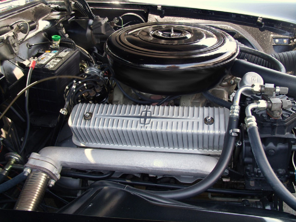
LOVE the valve covers idea...

Collecting Classic American V-8 Engine Valve Covers
Collecting classic American V-8 engine valve covers becomes art on the walls of “Boss” Bob’s Garage.
Machine an enclosure to have "ribs" like a classic early Mickey Thompson cover for Pontiac (& the Hemi looks a great candidate for 1590B3):
...or one of my all time faves a '56 Continental with vertical ribs (love how just the ribs are polished):
So many great-looking valve-covers to choose from, from all marques! Why limit yourself to V8s? Could go with a 1032L for an inline-six valve cover or a 1590BX2 for one of the great Straight-8s!
Cool Offy cover for a Slant-6\
How'bout this Holden 6:

Fireball STR8:

Brian Thomas' McCulloch-blown STR8-flathead Packard (hear it and ride along here on youtube):

Maybe some paint and polish:

I'm going to have to do a few pedals in this vein, but gotta figure out how to go about it first.
Thanks for the inspiration, Fig!
Passinwind
Well-known member
I've bought quite a few old radios, projectors, tape machines, etc, to try salvaging the tube amps, or at least some iron & glass. I tried to stay fairly mainstream conversion-wise, but couldn't resist the military aircraft audio tube amp-in-a-can. More on those later...This is a Model 384 15-watt 2-AX7, 3-6V6, made by Bell and Howell. I inspected the guts pretty closely, cleaned it up a bit, and slowly cranked the voltage using a variac. Here it is after idling 30 min. Next will be an audio test, but it's looking good!
I have a tweed champ-style combo cab that I think I can use or I'll build / have built a custom head cab (assuming all goes as planned).
Glow you little darlings!

Love that stuff. Here's one I found in a used tool shop in Seattle, it worked fine as-is beyond needing some love for its old school screw on coax mic connector. 2 x 6L6 and a couple of 6SC7 preamp tubes. A guitar player friend gigged with it professionally for several years and then I eventually traded something or other to get it back. Gave it away to a young DIYer several years ago.
