First Vero Build - Runoffgrove Tonemender

mjh36

Well-known member
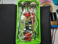
Not a pedalpcb build, but I thought I would show my mistakes and fixes as a good lesson learned.

Used spare parts to make this my first vero, and I made the cuts and links and all parts COMPLETELY mirror image of what it was supposed to be. Learned this after I finished the pedal and it didn't work.

But if you notice in the pic, I could make it work by bending the legs of the IC by 180 degrees and putting it in upside down. And it worked! I was sweating while bending it that's an expensive TLC2272.

Anyways, not the eq pedal I wanted but it turned out great, it let's me turn off the preamp and eq section in my Torpedo CabM, it's ultra clean, and it's like a fender/Marshall preamp more than like true "eq" pedal but I'm happy.
 

Attachments

  • 20201103_200248.jpg
    20201103_200248.jpg
    1.8 MB · Views: 48
I'm pretty sure he said he made both the Tonemender and Omni cab by vero, and would like to make them on pcb's. I don't know Portuguese but I know Spanish i got u bro. ?
 
I speak Portuguese. It is terrible to have to use a translator program. :)
The two pedals together worked very well. Tonemender is great.
 
Can you explain your "mirror image" problem? I'm interested in veroboard builds and want to learn as much as possible before building (even though you learn the most from building :))
 
I had this problem the first time I built too.

Most stripboard (also called vero) layouts online show two views, one with all the components and links and track cuts, and one view with just links track cuts so it’s easy to see them.

BOTH OF THESE VIEWS ARE TYPICALLY SHOWN FROM THE COMPONENT SIDE, not the side with the copper tracks. So, when cutting the copper tracks, you have to mirror it in your head from how it’s shown.

Since my first time mistake, now I always mark the cut spots with a sharpie on the non-copper side (where the components will eventually go). This way I can just follow the layout while marking without mirroring in my head. Also the marks are helpful landmarks while populations components. Then, I can see the sharpie marks through the hole on the copper side while cutting the tracks (I use a drill bit and turn it by hand until the track is fully cut around the hole). I also check myself by recounting in the mirrored way, but that’s just a double check for me.
 
But if you notice in the pic, I could make it work by bending the legs of the IC by 180 degrees and putting it in upside down. And it worked! I was sweating while bending it that's an expensive TLC2272.
I did the same once but broke a leg off while trying to do it. Good thing for me it was only a tl071, and I had another one on hand.
 
Last edited:
Can you explain your "mirror image" problem? I'm interested in veroboard builds and want to learn as much as possible before building (even though you learn the most from building :))
Phi1 explained it perfectly, gotta look at it from the component side. I watched this video it helped me figure out the orientation mistake I made.

 
I'm not sure if he suggests this in the video, but my boneheaded way of keeping track of the cuts is to download the image file, open it in preview, then flip it on the horizontal axis and just follow the picture.
 
Mirroring the view is a smart idea. I like to have both top and bottom views when I make vero boards. Bottom for cutting, top for populating. I use a sharpie to mark where the cuts go on the bottom, then double-check it. If I'm really feeling A-R, after I cut the board I scan it and then overlay the vero cu side image on the scanned board image to make sure the cuts are in the right place before I do any soldering.
 
This is another advantage of Photoshop.
You can flip the image Horizontal or Vertical or any degree you want.
When I do my Pedal Graphics, I flip the PedalPCB image so it is facing the top or face of Pedal so I know all my Pot, LED, Switches are in their correct orientation to the Board.
My Temporary Graphic is my Drilling Jig :
Terrarium  Drilling Template Pedal.jpg Terrarium Graphic with Board.jpg
 
I've done the mirror image thing and also just generally messed up the placement of cuts on vero, but I still love working with it for some reason.
 
A question about Tonemender: My pedal still has sound, even with the volume potentiometer at zero. Is this normal for the circuit or could it be something wrong?
 
A question about Tonemender: My pedal still has sound, even with the volume potentiometer at zero. Is this normal for the circuit or could it be something wrong?
My guitar is in the shop, so I can't check. But I think mine is the same, a little volume even at 0. It's very powerful.

I will let you know for sure in a few days when I get my guitar back.
 
My guitar is in the shop, so I can't check. But I think mine is the same, a little volume even at 0. It's very powerful.

I will let you know for sure in a few days when I get my guitar back.
Thank you for your help.
What is curious is that the OMNI cab does have the same problem. Even when I used each one in a separate enclousure
 
I sometimes used to reverse the image in photoshop to make cutting the tracks easier but these days I've got used to reversing it in my head. I do wonder if it's helped by being a photographer and being used to seeing things reversed? Less common these days with digital photography of course but back in the day printing from negatives and using medium format cameras you got used to reversing things in your head.

I think I prefer vero too. PCBs seem like cheating in a way and I have better luck with the pedals I make on vero.
 
Thank you for your help.
What is curious is that the OMNI cab does have the same problem. Even when I used each one in a separate enclousure
Hey just got my guitar back and yes, my Tonemender still has a little volume when at zero.
 
Back
Top