You are using an out of date browser. It may not display this or other websites correctly.
You should upgrade or use an alternative browser.
You should upgrade or use an alternative browser.
SOLVED Flock LED doesn't light up, no sound
- Thread starter Ctrl4Smilerz
- Start date
Ctrl4Smilerz
Well-known member
To clarify when engaged the rhythmic popping continues but the sound from the guitar is cut.
Ctrl4Smilerz
Well-known member
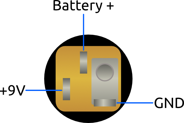
Yes, fixed that, thanks. That got the LED working, got rid of the popping and got me sound. Sounds very scratchy and the rotary switch doesn't change anything. What should I check next?I may be wrong, but it looks like your DC jack is wired backwards. Is that possible?
Last edited by a moderator:
Ctrl4Smilerz
Well-known member
Make sure you have the Oct 1 and Oct 2 controls turned up, the rotary won't have any effect without some of the octave blended in.
I went back to double check. I set both Oct 1 and Oct 2 to full (CW) and still no change with the rotary. Is there a way I can test the rotary with a multimeter to see if its a solder joint, or a bad unit?
Ctrl4Smilerz
Well-known member
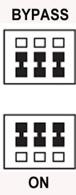
Once I fixed the polarity on the DC power I get sound. I am now trying to debug why the rotary switch isn't working.Check your Footswitch for Continuity to make sure you have no bridges between pins up & down.
You should not have any Continuity from left to right on middle pins:
View attachment 32299
Check to see if the Rotary centre pin is making contact with the main board.Once I fixed the polarity on the DC power I get sound. I am now trying to debug why the rotary switch isn't working.
Ctrl4Smilerz
Well-known member
I'm going to check all the solder connections tonight when I get home. Do you know how I can measure continuity of the center pin with a multimeter?Check to see if the Rotary centre pin is making contact with the main board.
Bricksnbeatles
Member known well
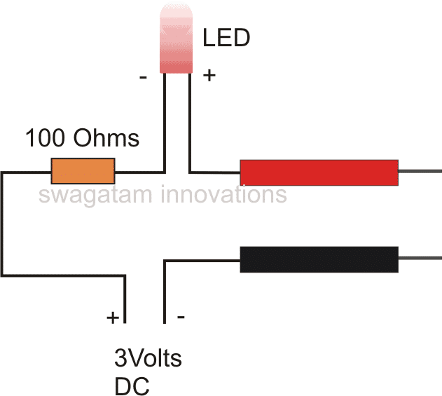
If you have a digital multimeter it likely has a continuity tester setting. Otherwise you can rig one up with an LED, a resistor, and a coin cell batteryI'm going to check all the solder connections tonight when I get home. Do you know how I can measure continuity of the center pin with a multimeter?

7 Simple Continuity Tester Circuits Explained - Homemade Circuit Projects
If you are looking for a simple circuit to test continuity of wires and long conductors, the explained 7 easy to build continuity circuits are the ones which you can […]
 www.homemade-circuits.com
Ctrl4Smilerz
Well-known member
Thanks. I was trying to figure out which pins to check continuity between. I understand the pins outside the circle are the selection, but I'm not sure what the center pin doesn't and how they correlate to the header pin that connects it to the main board.If you have a digital multimeter it likely has a continuity tester setting. Otherwise you can rig one up with an LED, a resistor, and a coin cell battery

7 Simple Continuity Tester Circuits Explained - Homemade Circuit Projects
If you are looking for a simple circuit to test continuity of wires and long conductors, the explained 7 easy to build continuity circuits are the ones which you can […]www.homemade-circuits.com
It will connect to 1 of the 10 inline pins , the other 9 being the outer PinsThanks. I was trying to figure out which pins to check continuity between. I understand the pins outside the circle are the selection, but I'm not sure what the center pin doesn't and how they correlate to the header pin that connects it to the main board.
Do you know how the DMM Continuity works?
Ctrl4Smilerz
Well-known member
Awesome, thanks. Yes I know how to use DMM in continuity mode.It will connect to 1 of the 10 inline pins , the other 9 being the outer Pins
Do you know how the DMM Continuity works?
Cool, Check the centre Pin for Continuity to to the matching pin on the Adapter board then from the matching pin adapter board to the main board & repeat the process for the other 9.Awesome, thanks. Yes I know how to use DMM in continuity mode.
Ctrl4Smilerz
Well-known member
Thanks, I will try this out tonight. Hopefully this will show where the problem is.Cool, Check the centre Pin for Continuity to to the matching pin on the Adapter board then from the matching pin adapter board to the main board & repeat the process for the other 9.
Ctrl4Smilerz
Well-known member
Okay, so I went through all 9 positions and ran a continuity test between the header pins and the center pin of the rotary dial and found no problems. I did notice when testing it out that only the base and master pots do anything. It gets a great fuzz tone, that sustains for a really long time, but no harmony. Is it possible there is a problem with one of the ICs? Maybe the LED ring I'm using has a higher resistance that is messing something up? Any other ideas on what else to try?
Ctrl4Smilerz
Well-known member
Okay I got it working! I went through and re-seated all the IC's in their sockets, and sure enough it worked for me. Thank you everyone for helping, and putting up with my noob mistakes.
Go to your 1st message & click on Edit & in the header it will give you an option on the left to mark it as SOLVED.Okay I got it working! I went through and re-seated all the IC's in their sockets, and sure enough it worked for me. Thank you everyone for helping, and putting up with my noob mistakes.
Click & Save.
Similar threads
- Replies
- 22
- Views
- 1K
- Question
- Replies
- 16
- Views
- 426
- Replies
- 7
- Views
- 671


