
You are using an out of date browser. It may not display this or other websites correctly.
You should upgrade or use an alternative browser.
You should upgrade or use an alternative browser.
FV-1
- Thread starter VeNoM
- Start date
Hi,
I have another question. I've built the Spatialist reverb but it didn't work. It turned out I've soldered the FV-1 the wrong way. I've desolderid it, turn it for 180 degrees and soldered it again on the pcb. The effect still didn't work, it just sounded like there was only dry signal. So I've desoldered the chip again and ordered a new one from Musikding (I've also ordered the whole Spatialist kit from Musikding). When I got the new chip I've soldered it on the pcb and the effect has started to work. But there is a problem. The programs are not from the Spatialist Reverb but they sound like the default FV-1 programs (the eeprom is still the original which I got with the kit). Is it possible that I got the wrong eeprom in the first place? Or something else?
Thank you and best regards.
Wow that some impressive determination. We always learn the most from mistakes, so way to power through.
Check the voltage at fv-1 pin 13. It should be 3.3v. Grounding this pin activates the internal patches (check out the fv1 data sheet). If pin13 is 0v, maybe you have a solder bridge or mistake, either on the fv1 chip or on the components connected to pin13.
Check the voltage at fv-1 pin 13. It should be 3.3v. Grounding this pin activates the internal patches (check out the fv1 data sheet). If pin13 is 0v, maybe you have a solder bridge or mistake, either on the fv1 chip or on the components connected to pin13.
I watched a tutorial about checking voltage. I hope I did everything rigth, it shows 3.29V. I've touched the pin 13 with the red wire and pin 11 (ground) with the black wire.
Also what does "0: Use internal ROM programs, 1: Useprograms from external EEPROM " (Pin 13 from the table below) mean?

Also what does "0: Use internal ROM programs, 1: Useprograms from external EEPROM " (Pin 13 from the table below) mean?
Last edited:
Sounds like you’re doing it right. You can touch the black probe to anywhere in the circuit that is ground, other points would be easier the pin 11 of the fv1.
Pin 13 of the fv1 is a digital input looking for either 0 or 1 (0 being 0v and 1 being the chip’s supply voltage, 3.3v in this case). Since your reading 3.29v (definitely close enough to 3.3 for the chip to read it as 1), it should be reading the patches from the external eeproms. You could test by removing the eeprom from the socket and seeing what happens (I think it would just make the wet side silent).
Pin 13 of the fv1 is a digital input looking for either 0 or 1 (0 being 0v and 1 being the chip’s supply voltage, 3.3v in this case). Since your reading 3.29v (definitely close enough to 3.3 for the chip to read it as 1), it should be reading the patches from the external eeproms. You could test by removing the eeprom from the socket and seeing what happens (I think it would just make the wet side silent).
Oh, I understand now, if pin 13 is tuching the pad then eeproms programs are being used, if not the internal are used, thank you.
Yup're right, if I remove the eeprom, the wet side is silent.
If it helps I'm attaching two pictures of my build:
Yup're right, if I remove the eeprom, the wet side is silent.
If it helps I'm attaching two pictures of my build:
Attachments
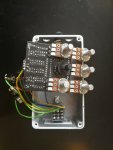
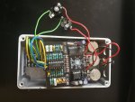
Do you have anything isolating the mix pot and vol pot from the pcb? Something like this? Or some foam tape?

 smallbear-electronics.mybigcommerce.com
Dust Cover for 16mm Alpha Pots
Guitar pedals, pedal parts and electronics.
smallbear-electronics.mybigcommerce.com
Well I guess. Make sure pin13 is 3.3v at the same time you’re playing through the patches.
Maybe try to see if your patches and their controls match the fv1 internal patch list (on the data sheet) exactly. That would be strange because why would musikding have an eeprom chip with those patches on it?
Or see if it’s actually the pedalpcb octagon or module8 patches, or some random combination of patches, then once you have the info see if musikding will send you the right one.
Pin13 is constantly at 3.29v
Also I noticed that the programs don't match the default one or octagon or module8 either
All are some kind of reverbs, but they don't seem to match those listedn od the spatialist reverb.
These are my findings (type of effect, pot1, pot2, pot3):
1 reverb, (length of the reverb, latency (if I turn it clockwise, guitar sound comes in with some latency), don't hear any difference)
2 reverb (length of the reverb, don't hear any difference, don't hear any difference)
3 reverb (length of the reverb, don't hear any difference, don't hear any difference)
4 reverb, (length of the reverb, latency (if I turn it clockwise, guitar sound comes in with some latency), don't hear any difference)
5 vibrato reverb (reverb mix, vibe mix, vibe rate)
6 shimmer reverb (length of the reverb, pitch of the shimmer effect, shimmer mix)
7 vibrato reverb (reverb mix, vibe mix, vibe rate)
8 shimmer reverb (length of the reverb, pitch of the shimmer effect, shimmer mix)
Robert
Reverse Engineer
You're definitely running algorithms from the EEPROM.
It sounds like your program switching isn't working properly.
Turn the mode switch all the way counter clockwise (Program #0) and measure the DC voltages on the right side of R7, R16, and R17.
Repeat this for all 8 positions of the rotary switch.
It sounds like your program switching isn't working properly.
Turn the mode switch all the way counter clockwise (Program #0) and measure the DC voltages on the right side of R7, R16, and R17.
Repeat this for all 8 positions of the rotary switch.
If I understand correctly, I have to measure with the red stick of the multimeter on the right side of the resistor and with the black on the left side (if I understand the scheme correctly this is ground).
I get R7, R16, R17:
1 position: 0v, 0v, 0v
2: 3.32v, 0v, 0v
3: 0v, 3.32v, 0v
4: 2.89v, 2.89v, 0v
5: 0v, 0v, 3.32v
6: 2.89v, 0v, 2.89v
7: 0v, 2.89v, 2.89v
8: 2.89v, 2.89v, 2.89v
I get R7, R16, R17:
1 position: 0v, 0v, 0v
2: 3.32v, 0v, 0v
3: 0v, 3.32v, 0v
4: 2.89v, 2.89v, 0v
5: 0v, 0v, 3.32v
6: 2.89v, 0v, 2.89v
7: 0v, 2.89v, 2.89v
8: 2.89v, 2.89v, 2.89v
I apologize for the late reply, I was bussy yesterday.
I only have an empty 23lc1024 (I also order it from Musikding) - I orderd the 24lc32a:
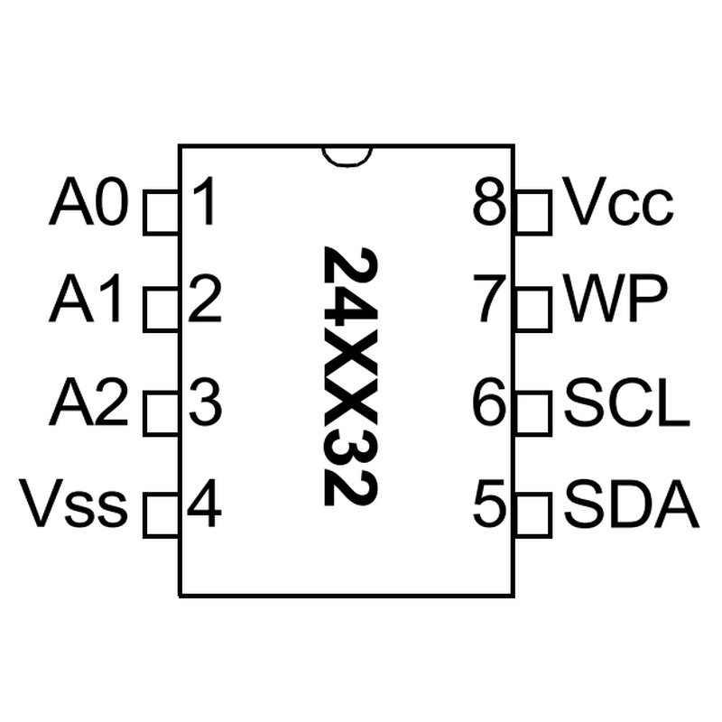
But there was probably a mixup and they send me the 23lc1024 instead.
I put it on the pcb, but there was no sound when the pedal was turned on.
I only have an empty 23lc1024 (I also order it from Musikding) - I orderd the 24lc32a:

But there was probably a mixup and they send me the 23lc1024 instead.
I put it on the pcb, but there was no sound when the pedal was turned on.
Similar threads
- Replies
- 4
- Views
- 285
- Replies
- 2
- Views
- 214