Gravitation reverb

steviejr92

Authorized Vendor
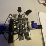
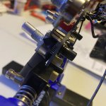
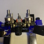
Hi guys I’m new to pedal building and this is my 3rd build the gravitation reverb. I had populated the board and I wired it to jacks and stomp switch I had bypass when it’s turned off but when engaged I get no sound even though the led light turns on. Which leads me to believe the problem is on the circuit board yet I have looked at others boards and mine doesn’t look any different I don’t if my parts are low quality if that a thing but all of my polarities on my electrolytic capacitors are right both my ic chips are on correctly, I do use bojack resistors from a kit but I don’t know if that will affect anything I did notice the legs are a bit thinner but others other than that they’re all the right values. I checked my pots and they’re on correctly and I do have the right belton reverb chip soldered directly the only the thing different I could notice was the voltage regulator the pub calls for L78L05 but I have LM78L05ACZ I don’t know if that’s it I read somewhere that the pin out might be different but I’ve gotten 2 different answers yes and no lol. I’m lead to believe this is the problem. Can anyone help me out here I’ve ordered a 2nd board and reverb chip since I feel like the parts could be duds……oh and I forgot to mention because of that confusion about the voltage regulator I’ve removed and tried backwards and the same thing and now I e ruined the eyelets where it’s needs to go idk if it’s salvageable but I’ll be posting pics please help lol
 
Here’s the current state of my circuit board but please be reminded that there was a voltage regulator in there the correct way and the opposite and both ways I was still getting no sound at all but my led was turning on
 

Attachments

  • EDB03FC8-A48B-4B7B-BAAE-96389752EFCE.jpeg
    EDB03FC8-A48B-4B7B-BAAE-96389752EFCE.jpeg
    1.2 MB · Views: 27
We're going to need some pics.

You can forget about the Belton module and regulator for now, you should have a clean signal even without those installed.
 
Your 3PDT breakout board is upside down, but ignore that for now, that wouldn't cause the problem you're having.

Also, did you insulate the potentiometers that are under the PCB?
 
I did insulate the pots with black electric tape. I did not notice the 3pdt board being upside down! I don’t have one of the heating guns to desolder should I just buy another? With a breakout board?
 
I wouldn't trust a 3PDT switch after removing a breakout board, but we can get to that after you get the pedal working.

That shouldn't affect the operation of the pedal.

Electrical tape isn't very good for insulating pots, component leads almost always poke through.
 
I have no covers I will need to order some to continue but I do have a new board on the way and another chip should use the spare parts I have to build another? In other words do you thing this is still salvageable?
 
Hmm I don't think that one is going to cut it, but just for the heck of it, put it on the 300VDC setting and measure across the DC jack and see what it reads. (with power applied to the circuit)
 
Yep, the regulator isn't important right now.

Okay, it was worth a shot... I was hoping it'd measure 9V but since it's reading low we don't know if we can trust it's accuracy since the 300V range is waaay out of range for what we're trying to measure.

If you get a DMM we can go further.

I've never used it personally but a few folks here use a relatively inexpensive meter from Harbor Freight.
 
That’s exactly where I’m going tommorrow first thing in the am that’s where I got this one I’m going to be getting to better one to continue this! Thank you for the support so far let’s hope this guy is still salvageable!
 
Back
Top