HM2 / Promethium distortion mod - bypass distortion?

mnemonic

Well-known member
Hi everyone,

I have just got a Promethium distortion pcb in the mail, I've waited long enough for Boss to make a Waza HM2, so I'll just make one myself.

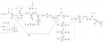
I was thinking of also making a tagboard HM2 EQ only for use with other distortions, or just for some 'HM2 flavor' without the clipping, but then I thought, shouldn't it be possible to just bypass the distortion section of the pedal with a SPST switch? I've (poorly) drawn over the schematic from the build docs in mspaint, just jumping from the input buffer to after all the clipping, would this work? Or do I need to use a larger switch and lift connections in the distortion circuit also?

Thanks
 

Attachments

  • distortion bypass maybe.jpg
    distortion bypass maybe.jpg
    82.7 KB · Views: 44
You'd need to put the switch earlier, between the transistor and the 47n cap, then have one lug to the circuit and one lug as bypass to where you have it.

I'd be interested to see if there were noise etc poking through because all the circuit is still on in the enclosure, just not engaged, but it's still getting power and doing it's thing, but rudimentarily I think your plan would work.

You could make it a pot too, for some blend action.
 
If you don’t want to have to roll your own for the EQ part, I know Kurt Ballou makes a pedal of just the EQ section. You can pick up the build kit for it at Small Bear and the PCB through God City Instruments.
 
You'd need to put the switch earlier, between the transistor and the 47n cap, then have one lug to the circuit and one lug as bypass to where you have it.

I'd be interested to see if there were noise etc poking through because all the circuit is still on in the enclosure, just not engaged, but it's still getting power and doing it's thing, but rudimentarily I think your plan would work.

You could make it a pot too, for some blend action.

so I should ‘intercept’ the circuit before the Q1 transistor (I assume input buffer)?

good point about using an spst switch so I lift the connection going into the distortion part of the circuit.
 
I got all my parts ready, and I realised I forgot to order two of the transistors needed for this one (2N5457 and 2N3906) :mad:

I have a spare J201 that I believe would work in place of the 2N5457 (a google search shows some people saying that in that position any n-channel jfet should work), but I have no other PNP transistors to sub for the 2N3906. I ordered some so completion will need to wait until those arrive.

in the meantime i have wired everything else up, and put sockets for the missing transistors.

I have done it like this, with a DPDT switch, hopefully it works!

distortion bypass v2 draft.png

unfortunately MS paint is the only software I have to edit pictures.

The color codes are the color of wire I used for each connection, since I put the switch under the board, between the knobs (a decision i may come to regret).
 
If you’re using a DPDT, definitely ground the input/output of the distortion block. Also, I’d put the switch after C1 rather than before so you maintain a DC-blocking capacitor in either arrangement (i.e., with and without distortion). The positioning after C12 is fine as-is.
 
If you’re using a DPDT, definitely ground the input/output of the distortion block. Also, I’d put the switch after C1 rather than before so you maintain a DC-blocking capacitor in either arrangement (i.e., with and without distortion). The positioning after C12 is fine as-is.
This is a good call I found out the hard way.

i noticed my missing transistors are in the distortion stage so I finished wiring in the footswitch and gave it a try, no noise in ‘normal’ mode which is expected, but in EQ-only mode, very sputtery. I added a cap after the 10k resistor on the input, (an odd value, like 82nf, just what I had since I ran out of 47nf’s), now it works great.

Very fun before a tight modern distortion sound. Like a more modern HM2, since it’s got the same EQ curve, just a different distortion character.

Cant wait for my correct transistors to arrive now.
 
Looking good! Glad it worked out for you. Did you end up grounding the distortion circuit at all (assuming you've received the transistors for that circuit block)?
 
Looking good! Glad it worked out for you. Did you end up grounding the distortion circuit at all (assuming you've received the transistors for that circuit block)?

I did receive the transistors yesterday and it’s now fully up and running.

I thought I may need to ground the distortion circuit when bypassed but I don’t notice any additional noise when it is bypassed so I just left it floating. I would need to pull everything out of the enclosure to get to the switch so really I’m just being lazy.

despite how high gain the distortion side is, I guess there isn’t much bleed-over there.
 
What a strange design. I see asymmetrical soft clipping, then crossover distortion, then symmetrical hard clipping. A PNP BJT amplifier (Q3) into a non-inverting OpAmp (IC2) for what reason?

Never have seen a distortion control like that either. Looks like it cuts input signal to the left and increases gain to the right, to provide a wider sweep than you'd get from a standard control.
 
I think the crossover distortion is just a consequence of implementing the rudimentary noise gate with the diodes. With everything else destroying the sound wave, that’s not going to be the most present distortion artifact.

Also, this circuit has gain stages all over the place. Most likely trying to keep noise low (evidenced by the gate block too) while keeping the op amp stable. At least that’s my guess.
 
Back
Top