SOLVED Hydra delay pedal doesn't fit template

ttango

New member
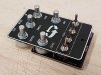
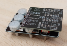
I've built the hydra delay and drilled the template. I have also purchased the face plate and the PCB doesn't fit. The On-On switches are off the face plate by a 1/16 of an inch. Has anyone ever mentioned this problem before? I used 16mm right angle through hole pots, but the only way this could possible fit is if I replace them with non pcb pots and wire them. This is nuts, as the documentation doesn't say squat.

thanks
How did you drill the template? Meaning did you print out the template? If so did you use size letter to print out the drill template?
Check your printer sometimes the printer defaults to A4 size printing. This will most definitely result in your holes being off by a bit.
 
Last edited:
This isn't the case. The Hydra has been built many times with the faceplate and drill template, the spacing is correct.

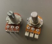
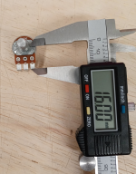
Can you post a picture of your pots? Every once in a while folks get some odd ones where the right-angle bend in the lugs is either further away from or closer to the body of the pot. I have no idea where they come from, but they throw off the alignment by a few millimeters.
 
Last edited:
I solved the problem by removing the pots and using wires so the template was drilled correctly as the plate lines up with the box perfectly. I used the one on the right and it didn't fit.
I needed pots with longer elbows. pots.jpg
 
I know, it's weird. I tried bending the elbow out but only 1/2 of the on-on pot would fit in the hole. And I recognize that a lot of people have built this particular build, but weird. Well, we will see today if it works. LOL
 
Looks like my pots. I couldn't fit it on the face plate. I even tried bending the elbow forward. All pots fit the plate but the switch rockers went in the hole but the threads wouldn't. And I wasn't drinking, I swear. If I hadn't already soldered everything I would retry it.
 
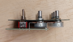
In the pic above I attached the hardware to the faceplate first, just because I didn't solder anything in place.

In my actual builds though, I assembled the PCB and installed all pots / switches, then mounted it in the enclosure, then added the faceplate / LED bezel last.
 
Yes, because it lines up with the faceplate. After I redid the pots with wires it all fits.
Screw it, Let me take the pots off and retry this, since it's obvious it fits. Give me a little while
 
There are some larger diameter toggle switches (6.35mm vs 6mm) that are becoming more common, so that could explain the threads not easily fitting the faceplate... but everything should align properly regardless.

I've thought about enlarging the holes, but then it'll leave a slight gap around 6mm switches.... I figured it'd be a lot easier to enlarge the holes if needed than to shrink them. :ROFLMAO:
 
well I am one stupid F###. I did not use the 16mm but the short one. as soon as I started pulling the Pots out of the drawer, the short ones were bent and had solder on the middle lug.
 
Gotcha. I was just curious because I see those pop up from time to time and had no clue where they were coming from.

The usual suppliers don't have them and they've caused confusion more than once.
 
Gotcha. I was just curious because I see those pop up from time to time and had no clue where they were coming from.

The usual suppliers don't have them and they've caused confusion more than once.
As a side note, here's a PSA for anyone that likes to tinker on Eagle CAD and is using Madbean's MBP_2017_v3.0 library:
All of the 16mm potentiometers in the library are these weird potentiometers that are not on 16mm centers.

I found out the hard way :(.

Edit: The potentiometers in the Effects Layouts Library 2.0 are correct and are on 16mm centers. Also, the PCB I designed for myself is not a currently available project at PedalPCB.
 
Back
Top