dorrisant
New member
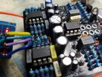
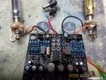
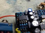
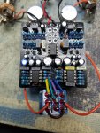
I built one of these... Checked every component as it went in. I have double checked everything and looked for solder bridges. There seems to be no reason for the way that it is operating. There is a barely audible signal with the switch in the up or down positions. It is loud and clear in the center position and all pots seem to do their job. I pulled the switch and checked for proper operation, no problem there. BOM calls for an On-On-On switch, doesn't specify Type 1 or Type 2. The operation of these switches may seem a bit odd but I am familiar with them from past experience. With the switch removed from the PCB I can jump the switch pads in the same manner as the switch would, makes no difference in the operation. Voltages at the IC pins look like they are right, but I can't tell for sure because they are not given with the build doc. All parts that I used are those called for on the BOM. This is no way close to being my first pedal build. I sell pedals on a regular basis, I have built hundreds from scratch, including making my own boards.
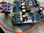
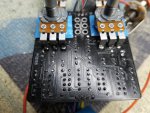
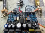
I would post pics but keep getting "The uploaded file is too large". Ok, but where is it posted what the size limit may be? The pics I want to upload are about 3.5MB each. I'm not going to play the resize game until I know what the max size is. Anyone know? I could almost bet money that some of you guys would love to see some of my builds, so please let me know.
Just wondering if anyone has built one of these and would be kind enough to share the voltages maybe...? Thanks for taking a look.
Tony
")