I gave up on easy 3pdt wiring boards

Olivier7960

New member
Turns out I don’t find so easy to wire after all. You have to solder it outside the enclosure because the soldering is done on the underside …. Through holes are super tiny … you have cut 4 pieces of wire the exact same length to have a neat build … do you solder the switch after or before the wires …? I sometimes have to use two pairs of « third hands » to hold everything …. Anyway I don’t like it. You guys have a good technique on how to use these wiring boards ? Maybe I’m missing something ?
 
The boards aren't necessary as the build docs will have the wiring diagram.

I will solder the board to the switch outside of the enclosure. I use solid core wire to attach the boards and will solder the wires to the completed PCB, install the PCB in to the enclosure, and then slide the switch down the wires and in to it's hole, tighten it up, then solder, then clip.

edit: clarification
 
Last edited:
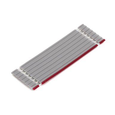
I just use a clothes pin clamped to the shaft of the switch with a weight on it to hold the switch stable. I solder the breakout board to the switch, feed the wires through the holes in the breakout board, tape them to the switch body with blue painters' tape, then solder the wires. After the switch assembly is complete, I solder the wires to the main board. Note that this process is a breeze with ribbon cable.
 
The base plate of this device holds a 3pdt perfectly. I use that to solder my switches and run extra wire. Trim to length at final assembly
Do you know where to get those alligator clip to fit those. Broke one on my third hand and can’t find that particular style with the “tube handle”
 
Ok just to see if I get this right you screw the switch in the enclosure then feed the wires from under the board so the soldering is done where it says « in out etc … » in that case you really have to make sure the solder flow through the hole cause the connections are on the other side right ? Kind of all new to this 😳
 
Ok just to see if I get this right you screw the switch in the enclosure then feed the wires from under the board so the soldering is done where it says « in out etc … » in that case you really have to make sure the solder flow through the hole cause the connections are on the other side right ? Kind of all new to this 😳
You can solder from either side of the board, that's totally fine.

Take a look at it and try a few dry fits to see what works for you. I'm sure that even people whose guts look very similar have totally different methodologies for getting there. It's what works for you.
 
Thank you for your input … this is more of a technical question but you have to make sure the solder covers the pads on both the underside and the top, right ? Sorry but again : new to this !
 
I've had a few issues with untraceable short circuits in 3PDT boards, especially with cheap 3PDT switches. Is there a trick to preventing that when soldering them?
 
I've had a few issues with untraceable short circuits in 3PDT boards, especially with cheap 3PDT switches. Is there a trick to preventing that when soldering them?
A. Don't use cheap switches.
B. Limit the time the iron is on the solder joint. If you don't get good flow after 2 or 3 sec, back off, wait a bit and go on to the next solder joint. You can always go back and touch-up the incomplete joints.

You don't have to fill the hole 100%. 25% is plenty.
 
I let the assembly cool completely between soldering each lug. I haven't had any footswitch or wiring board issues since adopting this practice. I do it for toggles too. The material that they seat the lugs in melts easily and the body of the 3pdt sinks a lot of iron heat. The low mass of the wiring board also makes them susceptible to overheated traces.
 
Back
Top