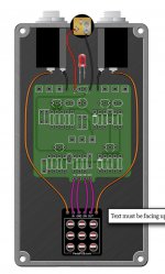
Looks great! I've just finished mine. 2 questions:
1) my led is not working. I soldered the longer leg into + (even though the instruction seems to say the opposite). Is this correct?
2) when disengaged there's no sound passing through. I used the true bypass wiring. Any suggestion?
View attachment 8190