Ionizer2 Oscillator Question

Danbieranowski

Well-known member
Hey all,
If anyone could help answer this question, I’d really appreciate it!

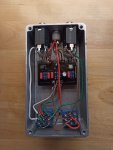
In this schematic, what controls the frequency of the oscillation?

9254C18F-73FC-42B8-AE2B-742F747A5AEC.jpeg
I’m assuming it’s the Oscillation pot, but before I go pulling stuff out of the board I want to make sure. The reason I ask is that this is the second one of these I’ve built, and in the first, the oscillation was a much higher register and note than in the second, which sputters at a very low frequency. I’m wondering if I need to swap out a component somewhere that might be restricting that frequency.

Thanks!
Dan
 
If it's similar to a voltage sag control then it must be connected to the power supply circuit

The way it's connected looks like your altering the ground connection via the variable pot resistance turn it down decrease resistance to ground and up to increase

I'm guessing that's how it works check your solder joints on C100 the power filter cap I can't see anything else that could affect it

Normally your filter cap would stop AC ripple noise / oscillation but in this case you actually want it! so that might have some bearing on it
Thank you tons! I’ll give that a look. Still learning and this stuff is super interesting.
 
I got a another question if I can piggy back on Your post xD. If I use a switch and ground the middle leg of the oscillation pot I can basically turn the pedal into a v1 ?
 
Found this some info in the comments from those that know much more than me

http://tagboardeffects.blogspot.com/2012/05/devi-ever-hyperion-2.html?m=1

Just read through the thread and I guess I’m not alone here. There are two things that stand out. One is that I’m using a 47u filtering cap, which it sounds like they are saying just skip this cap altogether? And the other thing is someone mentions not grounding through the board, but I’m using a PedalPCB 3pdt wiring board which does connect to the circuit through the board. Could this be an issue here?
 
No I don't think it's an issue many people have made this circuit successfully I'm assuming

The grounding comment just means don't have more than one ground on the circuit otherwise you wouldn't be able to make it oscillate

I think I'd keep the cap as I say I'm not 100% on C100s use but it looks like the pots variable resistance would affect charge and discharge times, in the tagboard build they used a 100u perhaps too large a value for more pronounced oscillation

With yours I'd make sure all your solder joints and values on the pot, R1 and C100 etc are good before you start changing anything

@Bobbyd67 you could bypass the pot and have a 'normal' ground set up if you look at the ionizer fuzz you'll see that's the only difference, if the pots at 0 ohms it should be a direct path to ground I'm not sure if R1 stops it going to 0 ohms though

I'd personally take it from the bottom of R1 and route it direct to ground or the pot lug 2 via an SPDT
 
Last edited:
No I don't think it's an issue many people have made this circuit successfully I'm assuming

The grounding comment just means don't have more than one ground on the circuit otherwise you wouldn't be able to make it oscillate

I think I'd keep the cap as I say I'm not 100% on C100s use but it looks like the pots variable resistance would affect charge and discharge times, in the tagboard build they used a 100u perhaps too large a value for more pronounced oscillation

With yours I'd make sure all your solder joints and values on the pot, R1 and C100 etc are good before you start changing anything

@Bobbyd67 you could bypass the pot and have a 'normal' ground set up if you look at the ionizer fuzz you'll see that's the only difference, if the pots at 0 ohms it should be a direct path to ground I'm not sure if R1 stops it going to 0 ohms though

I'd personally take it from the bottom of R1 and route it direct to ground or to the pot lug 2 using an SPDT
You rule. Thank you.
 
Hi again ! Gonna piggyback again. On this thread just cus I don't see the use of making a new one.

Finished my built with the foot switch to turn on and off the oscillation, made it just like I thought by grounding pin 2 and also tried r1 via the foot switch . The only issue is that whenever I use the switch it pops :/... I know that you can use a pulldown resistor on a circuit to take the pop away of the the bypass switch, but I just don't really understand how it works...

So my question is: is it possible to put in a pull down resistor somewhere in the pedal to make the popping of the oscillation switch quiet, and if so where do I put it xD ? I will try and post a pick of the gutshot tomorrow if that can help !!

Thanks !
 
In terms of my original post, I ended up just rebuilding from scratch and all was well. Guessing I had cold joints somewhere but I had all the parts and an extra board so I just took care of it that way.

In regards to a switch controlling the oscillator, what a cool idea!
 
Well here's a pic of the gutshot of my build with the oscillation foot switch. I am planning on doing some testing with alligator clips tonight to see if I can eliminate the pop via a pull down resistor, but I haven't the slightest idea how to do it xD if anyone can maybe point me in the right direction or have a idea how to it would be greatly appreciated !!! Thanks !!!
 

Attachments

  • IMG_20200717_120607_compress66.jpg
    IMG_20200717_120607_compress66.jpg
    442.3 KB · Views: 15
Back
Top