delackattack
Member
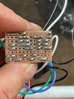
This was my first attempt with vero and im not too disappointed in the turnout but my buffer only produces little output when engaged.
Gotcha, i have done this a couple of times so far and the result has been the same. After hitting it with the probe, i start to loose signal after the first cut on the first row.Run a hot iron down the tracks of each row to clean them up. You may also want to take a solder sucker on some of those since it looks like a lot of excess
Get a magnifier and check for stray pieces of copper. Also, make sure your layout matches the layout. Once or twice mine have looked like I was drunk when I built it.Gotcha, i have done this a couple of times so far and the result has been the same. After hitting it with the probe, i start to loose signal after the first cut on the first row.
BIG SAME ON THIS ONEGet a magnifier and check for stray pieces of copper. Also, make sure your layout matches the layout. Once or twice mine have looked like I was drunk when I built it.
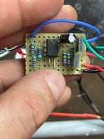
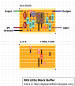
I could be completely wrong, but is your component layout flipped horizontally from the layout you posted?Get a magnifier and check for stray pieces of copper. Also, make sure your layout matches the layout. Once or twice mine have looked like I was drunk when I built it.
this could be the case as well, but i was sure i place my components on the side without copper tracesI could be completely wrong, but is your component layout flipped horizontally from the layout you posted?
The layout diagram is as-if you were looking through the component side. Your components are on the correct side of the board, but your layout and holes look like they are all mirror images of what they should be.this could be the case as well, but i was sure i place my components on the side without copper traces
FuckThe layout diagram is as-if you were looking through the component side. Your components are on the correct side of the board, but your layout and holes look like they are all mirror images of what they should be.
It happens. I would make a mirrored image of the layout and try again. Been there too.Fuck
I guess i need to start over and reverse the components???