BuddytheReow
Breadboard Baker
The Jordan Bosstone was released back in the 1960's and still makes its presence known today in the DIY community although some of the components have been updated to today's standards. It is a relatively simple circuit consisting of 2 transistors, 3 diodes (1 for polarity protection), 6 resistors (1 for the LED and separate from the circuit), 4 capacitors, and 2 pots. Here is a link to the build doc and the schematic is below https://docs.pedalpcb.com/project/ExecutiveFuzz.pdf.
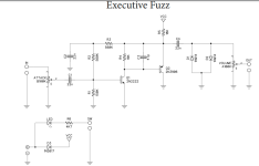
Ok. Intro is done. Let's move on to putting this on a breadboard to see if you like the circuit or want to mod it. My breadboard builds tend to be very compact for 2 reasons: I really don't like using the prefabricated jumper wires since they tend to be too long and I always try to keep some space on my board for any mods. For this build I want to set up my power section and start spacing out the transistors to see how much real estate I'll need on my board. I had to move Q1 shortly after I took the pics, but it's ok since nothing was connected to it.
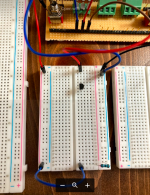
You'll notice that all power for this circuit goes through R18 before it touches anything else. To accomplish this I have my positive input on the left rails and ground input on the right. I added a jumper wire from left to right going through R18. The result is that I now have the right power rail properly set up for the rest of this circuit. I also wired up the Attack pot. Lug 1 to ground (blue jumper), Lug 2 into the breadboard as the start of the circuit, and Lug 3 as my signal input from the guitar.
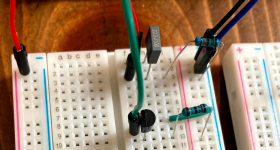
The next step I'm going to start to tackle the Q1 connections. I don't have a 2n2222, but I do have a PN2222 and they are pretty close in terms of specs. Check your pinouts to make sure your hooking this up correctly. C1 goes out of the attack pot and will go into the base of Q1, hence the jumper here. We also need to start biasing the transistor so I added R1 which goes from the capacitor to ground. I'll finish biasing in the next step and you'll see why Q1 is spaced so many rows from the input cap. R4 goes to the collector and comes directly from the power rail. Emitter goes straight to ground.
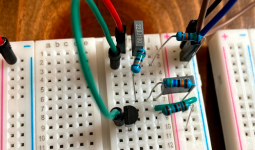
Now let's finish the biasing of Q1. We see that from the power rail we go through R3 and splits into C2 and R2. R3 and C2 act as an EQ filter (after finishing this circuit try pulling C2 out and you'll notice a difference in tone). R2 along with R1 set the bias of Q1. Think of biasing as turning on Q1 or tricking it into working.
Q1 is done so let's move on to Q2. A little theory first. Q1 is a NPN transistor and Q2 is a PNP transistor. The way that these are laid out in the schematic they act as one mega transistor with a synergistic effect. The gain of Q1 plus the gain of Q2 does NOT equal the gain of this circuit block, rather it is the product of the two (gain x gain). If you'd like to read more you can google 'Darlington vs Sziklai pair', but I also did a write up about it on Buddy's Breadboard and Circuit Design Notes specifically mentioning this circuit. OK the boring, but important stuff is out of the way. Let's continue. We now need to hook up Q2. To do this, the signal out of Q1 collector goes into the base but has to make a pit stop to hang out with C3 for a bit. C3 comes out of the power rails and is a coupling filter to clean up some noise.
You'll also notice in the schematic that Q2 is upside down, but that's ok; we just need to keep this in mind when wiring it up. Q2 is a PNP transistor so the polarities need to be reversed from Q1. Turning the transistor upside down works here, but not always the case in other circuits. A topic for another day. Emitter to the power rails (blue jumper) and the collector to ground (green jumper).
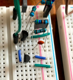
OK, almost done. Out of Q2 emitter goes C4. Out of this are a pair of hard clipping diodes. Each need to go in different directions with one end to ground and the other to the same row as C4. I chose to put this on a switch via my DPDT mod board shown in the bottom right since I wanted to hear how it sounds with(out) diodes. I'm assuming you don't have one of these nifty things and that's ok. If you want one you can find it at GuitarPCB. Otherwise, so make these diodes switchable, simply change the orientation of the diodes; those diodes should go from C4 down a few rows (make sure they're still in opposite directions) and then add a SPST switch from that row into ground. Also out of C4 is your output jumper. A lot going on in this one row, but it will work.
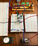
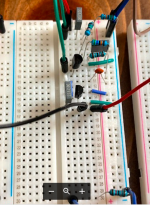
When I do my builds, if there's a volume pot at the end of the circuit I simply ignore it since it really won't change the tone. You are more that welcome to do so here to get the full experience. Instead of the output jumper wire to your out jack, that jumper should go to lug 3 of the volume pot, lug 2 goes to your output jack, and lug 1 goes to ground.
And that's it! The Executive Fuzz and inspired by the Jordan Bosstone.
Mods
C1, C2, and C4 can be changed to your taste here
The diodes we made switchable here and there is a big difference in the sound. Also try other types of diodes to see what you like.
A tone filter would go nicely here as well. A passive or active EQ filter is up to you. You can read more about them on one of my threads here if unsure how they work.
As an added bonus, let's look at the Ermahgerd! Fuzz. Here's a link to the build doc and the schematic is below. https://docs.pedalpcb.com/project/ErmahgerdFuzz.pdf
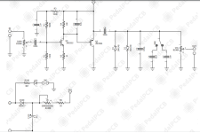
This circuit is merely a modded Jordan Bosstone! Solely looking at the schematics, here are the items you need to do to turn your freshly breadboarded circuit into another one:
-Change C1 and C4 to 100n rather than 22n.
-A 1k resistor needs to be added from Q1 emitter to ground.
-Instead of the 18k resistor into the power rail, swap it out for 1k and also add an Ermahgerd (starve) control
-Diodes should be changed from 1n914 to 1n4148. Make them switchable if you'd like.
-After the diodes, use a jumper and add a 470p to ground
-After the 470p cap, add 2 other caps to ground and make them switchable (4.7n and 18n)
-Change taper for the volume pot from A to B.
And that's it! Hope you all enjoyed baking on your breadboard!
Thanks,
BuddyTheReow

Ok. Intro is done. Let's move on to putting this on a breadboard to see if you like the circuit or want to mod it. My breadboard builds tend to be very compact for 2 reasons: I really don't like using the prefabricated jumper wires since they tend to be too long and I always try to keep some space on my board for any mods. For this build I want to set up my power section and start spacing out the transistors to see how much real estate I'll need on my board. I had to move Q1 shortly after I took the pics, but it's ok since nothing was connected to it.
You'll notice that all power for this circuit goes through R18 before it touches anything else. To accomplish this I have my positive input on the left rails and ground input on the right. I added a jumper wire from left to right going through R18. The result is that I now have the right power rail properly set up for the rest of this circuit. I also wired up the Attack pot. Lug 1 to ground (blue jumper), Lug 2 into the breadboard as the start of the circuit, and Lug 3 as my signal input from the guitar.

The next step I'm going to start to tackle the Q1 connections. I don't have a 2n2222, but I do have a PN2222 and they are pretty close in terms of specs. Check your pinouts to make sure your hooking this up correctly. C1 goes out of the attack pot and will go into the base of Q1, hence the jumper here. We also need to start biasing the transistor so I added R1 which goes from the capacitor to ground. I'll finish biasing in the next step and you'll see why Q1 is spaced so many rows from the input cap. R4 goes to the collector and comes directly from the power rail. Emitter goes straight to ground.

Now let's finish the biasing of Q1. We see that from the power rail we go through R3 and splits into C2 and R2. R3 and C2 act as an EQ filter (after finishing this circuit try pulling C2 out and you'll notice a difference in tone). R2 along with R1 set the bias of Q1. Think of biasing as turning on Q1 or tricking it into working.

Q1 is done so let's move on to Q2. A little theory first. Q1 is a NPN transistor and Q2 is a PNP transistor. The way that these are laid out in the schematic they act as one mega transistor with a synergistic effect. The gain of Q1 plus the gain of Q2 does NOT equal the gain of this circuit block, rather it is the product of the two (gain x gain). If you'd like to read more you can google 'Darlington vs Sziklai pair', but I also did a write up about it on Buddy's Breadboard and Circuit Design Notes specifically mentioning this circuit. OK the boring, but important stuff is out of the way. Let's continue. We now need to hook up Q2. To do this, the signal out of Q1 collector goes into the base but has to make a pit stop to hang out with C3 for a bit. C3 comes out of the power rails and is a coupling filter to clean up some noise.
You'll also notice in the schematic that Q2 is upside down, but that's ok; we just need to keep this in mind when wiring it up. Q2 is a PNP transistor so the polarities need to be reversed from Q1. Turning the transistor upside down works here, but not always the case in other circuits. A topic for another day. Emitter to the power rails (blue jumper) and the collector to ground (green jumper).

OK, almost done. Out of Q2 emitter goes C4. Out of this are a pair of hard clipping diodes. Each need to go in different directions with one end to ground and the other to the same row as C4. I chose to put this on a switch via my DPDT mod board shown in the bottom right since I wanted to hear how it sounds with(out) diodes. I'm assuming you don't have one of these nifty things and that's ok. If you want one you can find it at GuitarPCB. Otherwise, so make these diodes switchable, simply change the orientation of the diodes; those diodes should go from C4 down a few rows (make sure they're still in opposite directions) and then add a SPST switch from that row into ground. Also out of C4 is your output jumper. A lot going on in this one row, but it will work.


When I do my builds, if there's a volume pot at the end of the circuit I simply ignore it since it really won't change the tone. You are more that welcome to do so here to get the full experience. Instead of the output jumper wire to your out jack, that jumper should go to lug 3 of the volume pot, lug 2 goes to your output jack, and lug 1 goes to ground.
And that's it! The Executive Fuzz and inspired by the Jordan Bosstone.
Mods
C1, C2, and C4 can be changed to your taste here
The diodes we made switchable here and there is a big difference in the sound. Also try other types of diodes to see what you like.
A tone filter would go nicely here as well. A passive or active EQ filter is up to you. You can read more about them on one of my threads here if unsure how they work.
As an added bonus, let's look at the Ermahgerd! Fuzz. Here's a link to the build doc and the schematic is below. https://docs.pedalpcb.com/project/ErmahgerdFuzz.pdf

This circuit is merely a modded Jordan Bosstone! Solely looking at the schematics, here are the items you need to do to turn your freshly breadboarded circuit into another one:
-Change C1 and C4 to 100n rather than 22n.
-A 1k resistor needs to be added from Q1 emitter to ground.
-Instead of the 18k resistor into the power rail, swap it out for 1k and also add an Ermahgerd (starve) control
-Diodes should be changed from 1n914 to 1n4148. Make them switchable if you'd like.
-After the diodes, use a jumper and add a 470p to ground
-After the 470p cap, add 2 other caps to ground and make them switchable (4.7n and 18n)
-Change taper for the volume pot from A to B.
And that's it! Hope you all enjoyed baking on your breadboard!
Thanks,
BuddyTheReow

