You are using an out of date browser. It may not display this or other websites correctly.
You should upgrade or use an alternative browser.
You should upgrade or use an alternative browser.
COMPLETE Keeley Fuzz Bender
- Thread starter music6000
- Start date
Coda
Well-known member
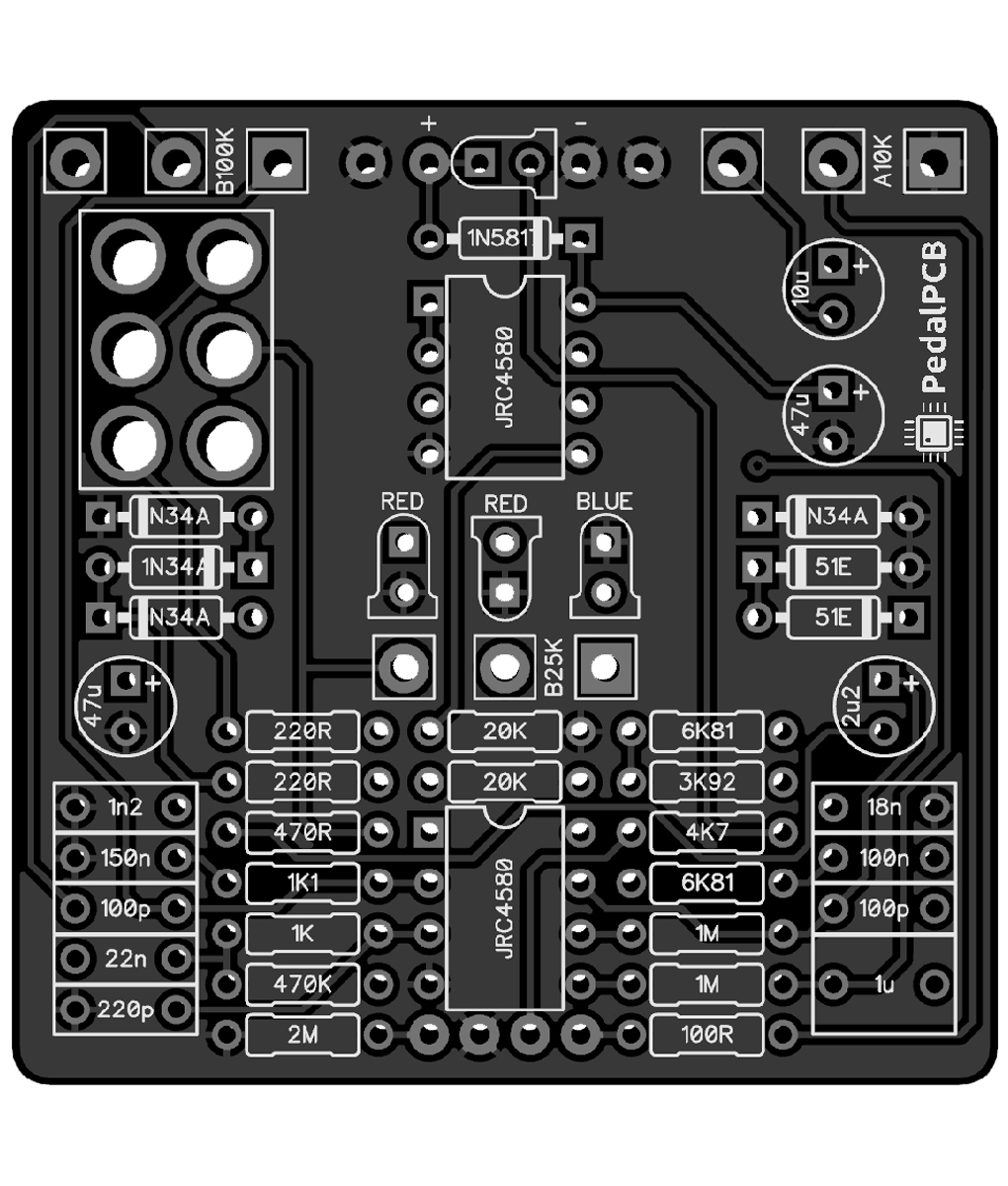
I ain’t done nuthin at all…reckon I won’t start with a riot…maybe a TS…The EffectsLayout schematic is correct aside from a few capacitor values.
I'll have the doc posted by the time the PCB is available (maybe sooner, who knows, let not get too overzealous), no need to start a riot or anything.
I ain’t done nuthin at all…reckon I won’t start with a riot…maybe a TS…

benny_profane
Well-known member
How consequential are those deviations?The EffectsLayout schematic is correct aside from a few capacitor values.
Coda
Well-known member
I pull into every thread shootin’ trouble…Got to find the reason, reason things went wrong
Got to find a reason why my money's all gone
Wait. This isn't a troubleshooting thread...
Robert
Reverse Engineer
How consequential are those deviations?
One is probably noticable, the others maybe not so much. I'll list them in just a bit.
@Robert curious what you used for the Ge NPN for Q3?
I'm waiting on prototypes but here's the specs of the original:
2SD352
hFE=123 at Ic=5.00mA
Vbe=0.223V at Ib=5.00mA
VceSat=0.016V at Ic=5.0mA and Ib=1.00mA
IcLeak=0.266mA
VanWhy
Well-known member
ThanksI'm waiting on prototypes but here's the specs of the original:
2SD352
hFE=123 at Ic=5.00mA
Vbe=0.223V at Ib=5.00mA
VceSat=0.016V at Ic=5.0mA and Ib=1.00mA
IcLeak=0.266mA
benny_profane
Well-known member
Is this the one you think might make a difference?C5: 2n2


