Kliche overdrive problem, no sound

Uglycatstudio

New member
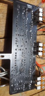
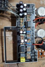
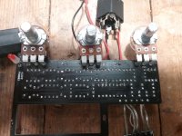
Hey everyone!! I finally took the plunge and ordered a Kliche overdrive (2 actually) to build. Followed the parts list and ordered off Tayda, spent an evening building and hit a roadblock. Led is always on, gets slightly brighter when engaging the pedal and passes no sound, on or "off". Checked all my connections and reviewed documentation numerous times. Throwing this out here as a hail mary. Any help would be much appreciated!!

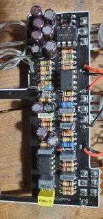
Ps: used russian diodes and identification rings are reversed, although I tried reversing them with no change what so ever.
 

Attachments

  • 16381157285373770307357607772717.jpg
    16381157285373770307357607772717.jpg
    1.2 MB · Views: 71
  • 20211128_120734.jpg
    20211128_120734.jpg
    1.4 MB · Views: 73
  • Like
Reactions: fig
You might have your switch the wrong side of the breakout board can't clearly see it, If that's the case then your switch possibly won't connect correctly

You could continuity check the S pads on the main pcb to make sure they go to the correct 3PDT lugs eg S1 goes to 3PDT lug 1 etc as in the pic

I think as long as S1, 2, 3 connect to their 3PDT lugs on the left and 4,5,6 on the right it'll be fine the way you have it

20211128_173202_copy_467x350.jpg

I haven't built it so not 100% If it matters seeing as it's the same both sides

We can't actually trace your offboard wiring to DC jack and in and out jacks post a couple of pics so we can see them clearly and trace the wiring
 
Last edited:
ditto on what Mcknib said, you also definitely need to clean and reflow, it looks like you might have bridges on the backside. Was the pedal powered when you tried the sound as well, buffered requires the power because the sound actually travels through part of the circuit. So if you have power, and bypass/on doesn't work, we need to look at the path audio travels from the input through the switch through the board and back out the output.
 
Thanks guys!! I just checked the switch layout and it matches what mcknib's diagram. I'm cleaning the flux and reflowing right now. I'll let you know in a few minutes if it worked.
Yes it was powered by 9v when I tried sound. No sound travels through in either mode
 
  • Like
Reactions: fig
Just reflowed and cleaned off excess flux, same issue.
I also checked, no bridges between solder (may appear in picture, but those are plastic hair from cleaning with a brush)
 

Attachments

  • 16381235278231679383924.jpg
    16381235278231679383924.jpg
    1.9 MB · Views: 45
If you're refering to the 9v, yes the center is positive on purpose. I ordered metal 9v jacks thinking they would be superior, but forgot the polarity is center negative and positive would conduct against the enclosure. Waiting on plastic jacks as we speak, the 9v adapter has been modified for this and is also centre positive
 
These may be backwards.

k5FfoV2.png

4vtXqZi.png


..and maybe a few others...unless they are bi-polar.
 
Last edited:
These may be backwards.

k5FfoV2.png

4vtXqZi.png


..and maybe a few others...unless they are bi-polar.
Hmmm, I'm checking my diagram and the C3 and C11 and is positive up. Do you have a pcb revision for the board you posted? Mines a pcb003, maybe the schematic I downloaded is not the right revision?
 

Attachments

  • 1638733495135138481469570208856.jpg
    1638733495135138481469570208856.jpg
    1 MB · Views: 11
Hmmm, I'm checking my diagram and the C3 and C11 and is positive up. Do you have a pcb revision for the board you posted? Mines a pcb003, maybe the schematic I downloaded is not the right revision?
Looks like the version currently online was updated in June. The image @fig posted is the main image from the PCB store site. Best way to tell would be to see what your board says but if you bought it recently I'd think that the docs are likely correct for your board. Can't hurt to double check, just in case.
 
Looks like the version currently online was updated in June. The image @fig posted is the main image from the PCB store site. Best way to tell would be to see what your board says but if you bought it recently I'd think that the docs are likely correct for your board. Can't hurt to double check, just in case.
Just confirmed, caps are oriented in right direction, so my schematic matches the board.
 
Back
Top