- Build Rating
- 4.00 star(s)
Ah, I remember when I first began this hobby like yesterday. That's because it pretty much was. Hard to believe that it was only just this past November when I built my first pedal. And although I can't keep the production line going as fast as @MichaelW, I've built a decent number of pedals over the last few months. Enough to where (although I am not) I feel like a seasoned veteran at times. A lot of this has to do with the help of this community; I tip my hat to all of you.
Anyway, back in the "early days" when I didn't know the difference between any PCB providers, I was taken in by a Black Friday sale of a certain European PCB company. The deals were ridiculous and I thought, "Holy S***! Look at all these dope boards! Time to load up!" So, I ordered like 10 thinking I was about to have a board full of Grade A tone and filth. However, when I later checked our forum here for any build reports or posts on any of these, my dreams were crushed. The consensus among the PedalPCB faithful was not good, and, feeling foolish for not checking our community before going wild on Black Friday, I put these boards at the bottom of my pile.
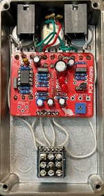
Now that I'm on a mission to compare RAT circuits for fun, I remembered the La Rata board in my pile and thought now was the time to bite the bullet and see for myself what Guitar PCB Mania was all about. I wasn't enthused when looking at it after I pulled it out. Having been spoiled by the glory that is a PPCB build, I felt like I was about to enter the dark ages...like going from a Mach 4 back to a single blade. Certainly, I thought to myself, no matter how clean this build will be, this thing isn't going to work. It'll be a waste of a Saturday morning, but I have to know.
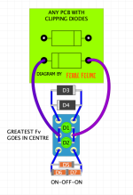
Well, what I now know is that, to my surprise, this is a legit RAT that sounds fantastic. Like others out there, this board allows you to build any of 4 different variants and add a second (or third?) clipping option for a 2-in-1. I went with the classic variant with 1N914's and Turbo Rat LEDs for my second clipping option. I was confused (and still am) if there is a 3rd clipping option using D6 (which I put an LED in) because the build requires an on-off-on switch, but with the third switch setting sounding the same as middle (Turbo Rat), I was at a loss. This was unclear in the build document.
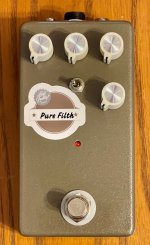
In addition to the 3 traditional knobs, I added a 4th "Sweep" knob, a classic mod that works well. There is an additional "Softness" control (meant to interact with the clipping) but I opted for the trimmer instead of the external because others in our forum here stated it didn't do much (which is true). However, when using a center punch prior to drilling, I forgot I had made this choice and began punching where this 5th pot would be. Hence the decal, which I had made for fun when I first started building. Luckily, the colors matched. I find it amusing for now (Rat's are indeed pure filth, are they not?), but will take it off when I tire of it; nothing wrong with displaying some battle wounds.
I compared the La Rata to my Fuzzdog Rodent (I gave my Muroidea to a friend and am in the process of replacing it), and it held its own. Is this comparable to a PPCB build? Heck no. But I'm happy to give it 4 stars. Isn't near to the user-friendly design of a PPCB (or even a Fuzzdog) board, and I'm still befuddled by the whole 3-way switch clipping thing, but this is a darn good rat. So that's 1 for 1 one with Guitar PCB Mania builds for me. Granted it's just one, but gotta give credit where credit is due. I wouldn't pick this over the previous boards I mentioned, but if you come across one or they have a big sale, I'd have no problem recommending it.
Thanks for reading. I know my build reports tend to be long and basic, but I like sharing them. Next Rat for me is the Effects Layouts version. If there are others you all recommend that I check out, let me know!


