Little Monk 5F184+

Big Monk

Well-known member
While we’re sharing…

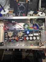
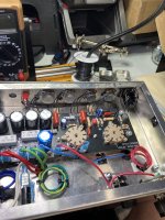
Not completed yet but in good enough shape for some progress pics.

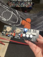
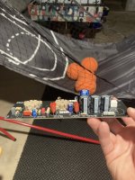
I’ve basically reverse engineered the Black Version 3 Valve Junior board while adding some logical additions like a slot for a treble peaker cap, fixing the input resistors, adding NFB capability and adding a screen resistor for the EL84.

I made the faceplates in DipTrace as well.

A few notable snafus so far: I used my Large diode footprints for the UF4007 rectifier and heater diodes but did not increase the pad size when I copied them to my amplifier parts folder. So I had to solder the diodes to the top of the board. They are very sturdy so I’m not concerned but I did feel like a dope.

For some reason, my 1W resistor patterns were to narrow and the leads are slightly sucked in, which is fine but still annoying.

My 100n 630vDC footprints were the same error. Too narrow. Not a big deal.

I’m waiting on a 47u power supply filter cap because I ordered a 100u with spade style leads and it didn’t fit.

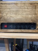
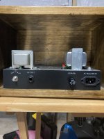
New JCM style lighted switch, IEC connector and rotary impedance selector. I expanded the Valve junior control set for by adding a Master (replaced grid leak with 250k), Volume becomes “Drive”, Presence Control and NFB control. NFB can be defeated and a normal 2.2u cathode bypass cap switched in.

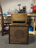
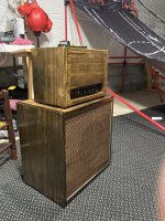
Added a new handle to the head cab, finally put some grill cloth on the speaker cab and went with the black Marshall knobs.

Just need to make spade connector terminations on the transformers and output section and then fire her up:
BEB653A1-8A82-4A40-9248-6F4B893A62A1.jpeg BC936921-DE84-447C-85BA-259DE6F23AD6.jpeg 056BA555-D6B8-4656-B52F-37638ED103F2.jpeg 1FB86ED9-3B6F-4A5A-9F13-A88221161B91.jpeg
 
Got the PT and OT terminations done, grounding done and neatened up spare PT/OT connections. Impedance selector is done and NFB insertion termination done. Just need to wire the IEC socket, fuse and power connections then the pots and NFB switch:

B1C5EC35-160E-460F-A279-CC516F23D3A6.jpeg
 
I am stalled in final control wiring and testing due to simple time constraints but I thought I’d take a second to issue a PSA to all would be amp builders and restorers or fixers:

Build yourself a Dim Bulb Tester.

IMG_0146.jpeg
IMG_0147.jpeg

What is a dim bulb tester you say?

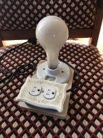
Essentially, it is a diagnostic device that uses a light bulb as an indicator to whether you have a short circuit current condition in your power supply.

If all is well, light glows dimly. If something is amiss, the bulb will glow like the sun.

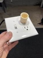
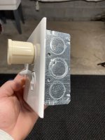
Circuit wise, you have a SPST light switch in series with the mains, in series with an incandescent 100W light bulb, in series with an outlet that you plug your device into.

When normal current flows through the power supply of the amp under test, the bulb glows dimly. If you have a short in the power supply or other issue causing short circuit fault current conditions, that current spike visually, and crudely, displays as a very bright bulb.

This is really required testing for initial startup of new amps, starting an amp after prolonged storage, or starting any vintage devices for restoration.

I built this with about $10 in parts from Lowe’s and the old hardwired mains plug from this same amp.
 
Finished up the control wiring and fired her up today:

IMG_0220.jpeg

Fairly certain I have a bad preamp tube. I first noticed because the circuit should be much louder with the NFB circuot switched out.

I did some troubleshooting and the NFB circuit was not the culprit. Brand new power tubes and voltages leading up to the preamp tube were fine.

Signal loss and lower plate voltage on the 12AX7 make that the likely culprit.
 
So, after a few sessions of completely chasing my tail, I got a lesson in how we can all be a dumbass sometimes.

Turns out I had all the pot values reversed, i.e. 5kB Presence hooked to Volume, etc. SO I reversed those and then had a fairly large ground hum and also some major attenuations of high frequencies.

I removed the board, fixed all the pot connections and went through and reflowed a ton of joints.

After all that the cranked Marshall on 11 sound was back with the NFB loop switched off but I was not getting the tones I wanted with the loop in. Furthermore, the NFB control was reversed such that turning it up actually decreased the NFB. Also, I had used a 68k limiter on the NFB control which meant it was not doing all that much. Swapped 16k and that did the trick.

Clips to follow at some point. Things have been super busy the last week.
 
Build yourself a Dim Bulb Tester.

We used to have a couple gadgets like this in the TV repair shop where I worked.

There is another benefit, the bulb acts as a current limiting device. We'd occasionally use these when firing up a television after performing repairs to the power supply or horizontal sweep/high voltage circuit. Even if the power supply had a dead short the bulb would limit current, preventing a catastrophic failure.
 
When we first moved into our house, there were some overly ornate switch plates in some rooms. Even though I couldn’t imagine wanting to use them (well, possibly if we were presented with a Disney loving grand-daughter) I tossed them in the attic. It only seemed natural to dress up my tester. Having a switch on it is a great idea…
3EB61EE9-E8DB-40BF-B09C-04E495220932.jpeg
 
Had a chance to play some more today.

I've been modifying the Valve Junior for close to 14 years and I think I'm done. I'm not sure you can get a 5w amp to sound much better than this.

Unfortunately I lost the PCB design files for this but will be putting a revised board together.

When I do, I’ll make the project files available for anyone wanting to build it, including the enclosure I used, transformer specs, etc.

All the onboard components with the exception of the Belton sockets came from Tayda.
 
Last edited:
This looks awesome. I've been wanting to make a small amp pcb ever since I made my first working guitar pedal pcb. Do you have any tips? I still haven't figured out if it's ok to do a ground plane on a tube amp pcb or it's going to cause any issue.
 
This looks awesome. I've been wanting to make a small amp pcb ever since I made my first working guitar pedal pcb. Do you have any tips? I still haven't figured out if it's ok to do a ground plane on a tube amp pcb or it's going to cause any issue.

This was my first amplifier PCB. I used a full ground plane on both sides.

I’ve learned now that I am only really satisfied with fit and finish if I use my own patterns and components in DipTrace.

I pull lots of data sheets and check measurements to the point of holding up finishing the boards sometimes.

This one in particular was a dream of mine as I’ve always wanted to have what is basically a drop in board for the Valve Junior with some of the standard mods, like EL84 Screen Resistor built in, etc.

I’m a little late for the VJ but AES has the perfect sized enclosure for this project and the Weber RVBPT works well for small SE tubes. I have the 15W Classic Tone Champ PT so I’d have to source a spec sheet and model number for people to use when I get this revised.
 
Back
Top