Low Tide LFO

Bio77

Well-known member
I wanted to poke around the Low Tide LFO section and see if I can identify changes that would increase the signal. However, in order to breadboard it you need to start with the Atinny chip. The schematic has pins 1, 3, 6, and 7 of the Randomizer not connected to anything. Is this right?

Also, I'm looking for opinions on what values I could change to increase the LFO signal. Right now, I'm thinking lowering R64, look like it would help.

Here is the schematic:

https://docs.pedalpcb.com/project/LowTide-Schematic-PedalPCB.pdf
 
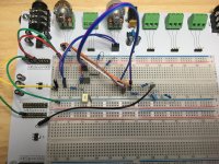
So, I finally got the breadboard working :D

I breadboarded the circuit from the first half of the slew pot through to leg 3 of the depth pot. The input was a 2V 20Hz square wave. Output signal was a 700mV triangle-ish wave affected by the second half of the slew pot.

If you want to increase the signal amplitude of the LFO section you need to lower the value of C38. It's 100n stock, I think 82n will increase it enough. I'm going to socket it in my build and try different values. I'll report back which one I end up with.

Now what I'm wondering what's up with the slew pot? The B half of the pot effects the shape of the output signal, it warps the triangle slightly in the first part of the rotation then pushes it more towards a square wave around 50% of the turn. The last half of the turn flattens out the signal completely. The A half of the pot just cuts the input signal as it is turned up.

I'm wondering what the function of the A half of the pot is? My input signal was 2V, maybe the output from the Attiny is larger and the A is needed. Any ideas?

I'm contemplating using a single pot instead of the double. Or I'll build it with the double and try shorting across the A part once its built to see if it functions better.
 
This was to mimic the randomizer output?
Yes. The randomizer is followed by a unity gain buffer and next an integrator. I wasn't sure that the gain of the integrator could be changed. I just tried swaping part values of everything and got lucky :D

I couldn't use the randomizer because I wouldn't be able to see it on the scope.

This circuit has a lot of weird things I wish someone could explain. The slew pot for one seems funny. Also, I'm not sure why they use a MCP602, its a split rail op-amp, but they run it at +5V and ground??
 
  • Thinking
Reactions: fig
Also, I'm not sure why they use a MCP602, its a split rail op-amp, but they run it at +5V and ground??

It’s a rail-to-rail op amp, but the documentation seems to imply it’s optimized for single, low-voltage supply:
This product offering operates with a single supply voltage that can be as low as 2.7V, while drawing 230μA (typical) of quiescent current per amplifier. In addition, the common mode input voltage range goes 0.3V below ground, making these amplifiers ideal for single-supply operation.
 
Back
Top