Low tide modulator wrong IC and hot regulator

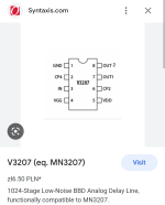
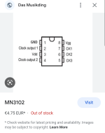
Just tried to power on my Low Tide Modulator build for first time and noticed the regulator getting too hot to touch. After some double checking I noticed I had the wrong chip at IC7 (MN3102 clock generator instead of MN3207 BBD). Oops. I swaped it out for the MN3207 and tried to power on but im still getting a hot regulator.

What damage might the MN3102 in place of MN3207 have caused? Could the hot voltage regulator be related?

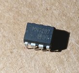
I suppose it's a good lesson to double check part markings. I ordered 2 MN3207 and 1 MN3102 from Cabintech Global and they put them all in the same DIP tray.
 

Attachments

  • Screenshot_20230115-012136~2.png
    Screenshot_20230115-012136~2.png
    144.5 KB · Views: 8
  • Screenshot_20230115-012117~2.png
    Screenshot_20230115-012117~2.png
    169.1 KB · Views: 8
Not sure if this helps any but i powered the circuit with the MN3207 removed and the regulator does not heat up anymore.


The MN3207 look a little suspicious to me as they appear to be resurfaced on top (rougher texture and sharper top edges). I haven't had issues with cabintech global parts in the past so I don't think they'd sell fakes or products they haven't verified.
 

Attachments

  • DSC_3230~2.JPG
    DSC_3230~2.JPG
    476.3 KB · Views: 15
CabinTech is a reliable resource for BBDs and clock ICs - so they should have been good. However, plugging the clock into the BBD socket will ruin that chip. You may need to replace the clock chip at least. And likely the BBD too if it was put into the clock socket. Double-check the voltage outputs on the regulator with both the BBD and clock ICs out of the circuit; to see if it is still good too.
 
The MN3102 clock chip was not for this circuit so it's ok it's ruined. I also didn't put the correct BBD MN3207 in any other socket so that wouldn't be the problem, although I haven't ruled out a bad chip as it is NOS and cabintech says 10% failure rate. I have one more MN3207 to try once I check those voltages as you recommended.
 
With the BBD out of the circuit the voltages are 9V in, 4.95V out. I put in the other MN3207 I had from the same order and the regulator stays cool and still outputs 4.95V. I think it may have been a bad chip.

Anything else I should be testing?
 
I am seemingly unable to get anything other than distorted audio out of this pedal. Audio passes through fine, mix control works when pedal is on but at full wet it is mostly distorted. I even tried many combinations of trim pot settings for gate and BBD bias. The sound is barely changed only more noise or oscillations present.

One extra error I found was a 1000000p cap at C13 instead of 100p. Gotta look closer at the parts im using. Shipped from one of the big stores as a 100p but has 105 marked right in it! Anyway, no better with the proper 100p in place.

I have two V3207D chips on order from cabintech. Hopefully that will be the answer.

The other thing I have noticed is quite a few others having similar issues replacing the 2SK208-Y with a J201 and that seemed to solve their issues. I currently have an SMD Toshiba 2SK208Y for Q1 and an SMD MMBFJ201 for Q4.
I see many say the J201 is a direct replacement for the 2SK208 but the pinout is different so that leaves me confused. The drain and source are on opposite sides, does that not matter?
 

Attachments

  • Screenshot_20230115-233219~2.png
    Screenshot_20230115-233219~2.png
    278 KB · Views: 10
  • Screenshot_20230115-212326~2.png
    Screenshot_20230115-212326~2.png
    82.5 KB · Views: 10
  • Screenshot_20230115-212222~2.png
    Screenshot_20230115-212222~2.png
    129 KB · Views: 10
The MN3207 look a little suspicious to me as they appear to be resurfaced on top (rougher texture and sharper top edges).
I'm not an expert, but that looks unlike any Panasonic/Matsushita MN series chip I've seen in older gear, or ones I've bought from Small Bear in the past. The font is wrong, the (M) logo looks particularly wrong, and I think they're supposed to have the dot and half circle on the end with pins 1 and 8, that only has the half circle.

If the the regulator is getting hot with the 3207, there's probably a short in the chip (unless a leg didn't get inserted into the socket and is shorting again another leg?). Probably a bad chip, possibly a fake it looks sketchy.
 
Is there a good way to check if the BBD chip is the problem? Or if it is related to the LPG chip?

I barely get a sound out of the pedal when mix is at 100%, just a quick pop on the pluck of a string and the sound quickly decays to back to silence. This makes me think there might be issue with the LM13700 but I know the LPG is supposed to be closely tided to the BBD in this pedal as mentioned in the trimming instructions.

With the Mix down a bit (under ~90%) I get the clean, loud signal at the output. So I think that the input and output circuits are working well.

I've checked the randomizer output on my oscilloscope while adjusting the rate and slew pots and it checks out as well as the clock output from the CD4046 which follows the changes with the rate and slew controls.

I have also gone through every resistor and comfirmed colour codes match the BOM values. All solder joints look good and no bridges found.

So this leaves me to believe it is the MN3207, LM13700, or possibly even the LM258p.
Hi squarewavesurfer! Could you post some screenshots/photos of the signal you get from pin 5 of the Randomizer chip?

I built my unit but the kit came without the Randomizer chip so I'm trying to bodge up a firmware for the attiny by myself and I'd like to see some waveforms...
 
Back
Top