TUTORIAL Mach 1 Overdrive - Greer Lightspeed OD

BuddytheReow

Breadboard Baker
One of the more popular overdrives on the forum recently (at least over the past few months), I wanted to see what all the fuss was about. Rather than being selfish and finding out for myself, I decided to document my build and share it along with anyone who may be interested in seeing why this keeps popping in the Build Reports.

Others claim this is a very good "transparent" overdrive, meaning it doesn't color your signal such as a tube screamer. After building this myself I would agree with these claims. What to find out for yourself? Well, make some room on your bench and dive right in with the Mach 1 Overdrive!!

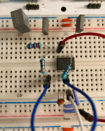
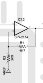
Like some of my other recent tutorials, here is the schematic, build doc, and my breadboard build. We're going into OD territory now with the "standard" diodes-in-the-feedback-loop type of build and I hope you learn a thing or two in the process.


1655732437600.png

1655732454572.png
 
Alright, let's get started. The power section. This one is a little different than others and I'll show you how I accommodated it on my breadboard.

1655732582768.png
C100 is just a filter cap to ground; throw that in the bottom rails. For the opamp itself I decided to put it in the middle of the board to give myself a lot of room to work for the feedback loop (more on that later). Pin 4 to ground and Pin 8 to 9v for the opamp. I am throwing a jumper to the bottom power rail since this is a one chip circuit and all the other power connections are VREF.

R101 and R102 form a voltage divider, but not in the regular sense of identical values. If you google a voltage divider calculator you'll find that our output voltage should be pretty close to 4.9v. With my components I measured 4.7v and for me I was ok with it. C101 comes out of this voltage divider to ground to act as an additional filter.

Here's the catch: I threw in a jumper from this junction to the TOP positive power rail. If you look above in the schematic there are 5 other VREF connections, but not a VCC connection. This made things a bit easier for me.
1655735052890.png
 
Now the input section.
1655735661329.png

As mentioned above, I knew the feedback loop will take up a lot of space, so I'm keeping the input section tight and merely jumpering it to pin 3 of the opamp.

Input, R1 to ground, and C1 below all meet in the same junction. At the end of C1 we have R2 coming from our VREF power rail. This then goes to the non-inverting section of the opamp (pin 3).

1655735628726.png
 
I'm building this out of order, but you will see how it all fits together. Like I said I needed some real estate to work with the feedback loop so let's work around that for now.

1655736671553.png

C7 can go right in the columns with pins 1 and 2. I then placed R10 between pin 1 and pin 5 to "link" between the two opamps. C9 goes to ground and can go straight into pin 5 column.

1655736621517.png
 
Now let's start on feedback loop. We'll do the diodes and gain stage next, but let's start with the RC filters.
1655737439954.png
ALERT! After I took this pic I realized it would be neater in the long run to move this section over to the left a number of columns. I also had to reverse R12/C5 and C6. In the revised pic below, C6 is on the left and R12/C5 is on the right. I am showing this to give you a sense how to layout these filters in relation to the remaining loop. There will be jumper after R11 to pin 2 of the opamp.

1655737404610.png
 

Attachments

  • 1655737366166.png
    1655737366166.png
    820.2 KB · Views: 4
  • Like
Reactions: fig
Now the diodes, gain stage, and close off that feedback loop.

1655739109387.png
Feedback loops can get tricky and be problematic if you're not careful.

The first step would be to install D6, D5, and D2. The end of D2 should be jumpered to pin 1 of the opamp. You can see that with my black jumper. The column at the end of one diode should also have the beginning of the next diode in series. I have circled D6 in my pic. I looks like it is in the same column as D4, but it is not. It's just a bad picture.

D4 and D3 start and end in the same columns as D6, D5, and D2 (columns 35 and 41 below), but the connecting columns are different. In my pic below, the connecting column for D4 and D3 is on column 38. D6, D5, and D2 connect at columns 37 and 39. I know it sounds and looks a bit confusing, but I will try to take a better picture when I can.

We also need to link up the gain control with this feedback loop. Try to make your layout match the schematic as much as possible to avoid confusion. Jumper in column 35 below to connect to pin 1 of the gain pot. R9 connects from pin 2 of the pot back into the feedback loop at column 41 of my pic.

Now, do you see where I moved the RC filters from above and flipped them around? There is a blue jumper unplugged at one end, but I took it out to show you the layout. It should be plugged back in pin 2 of the opamp.

If you are still a bit confused either DM me or ask below if my explanation isn't the best. From the post above I can see where a novice circuit builder may have an issue trying to connect the dots.

1655739086892.png
 
OK everyone. Stop. We should have completed the feedback loop to make this circuit work as is. Test it by plugging your output wire into pin 5 of the opamp and play something. Your gain control should work as well. If it doesn't or if you have no signal, check your connections.

Has it worked? Yes? Great! Let's move on to the next gain stage.
1655740034416.png

Pretty straight forward for this piece. We've already installed C9 above. R4 needs to go between pins 6 and 7 of the opamp. R3 goes from pin 6 to VREF (that's our top positive power rail described above). I added the black jumper to start our next stage. It goes into pin7 (opamp output).


1655739970688.png
 

Attachments

  • 1655740001156.png
    1655740001156.png
    16.3 KB · Views: 1
OK. Home stretch now! We need to add the tone section and the volume pot and we're done!

1655740251804.png

C2 is way too fat for this pic, but it comes from the black jumper. R5 comes out of C2 and goes into pin 3 of the TONE pot. Pin 2 of the pot goes to ground (not VREF). Also out of pin 3 we jumper to the volume pot pin 3. Pin1 of volume pot to ground and pin 2 to output. Relatively simple, yes?


1655740233556.png
 
Voila! The Mach 1 Overdrive stock circuit. I know that main feedback loop with the diodes is a little tricky, and to be honest they are not the best of pics. Test your circuit and see if it works. If it doesn't you either have a break in the connections somewhere or a component not pushed down all the way in your board. I hope you all had fun trying out this transparent overdrive circuit on the board.

Now go play something!!

BuddytheReow

1655740511716.png
 
Back
Top