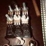
I'll post pictures tomorrow but for now can anyone tell me what the 2 trimmers are for? As of now I have no wet signal and turning any and/or all knobs does nothing Super bummed it didnt fire right up as I took my time building it. I'm kinda aware (so I read) of some issues with the pedal but not sure if any of the common issues apply to this board. Any who I'll get into it more this weekend and hopefully get it sorted out
So after flipping Q2 around I got the rate LED to flash and the on off LED. put it in a box and only the rate LED works pulled it out and nothing no power no lights. so Ive got some intermittent power problem somewhere I'm thinking. Oddly at one point Q1 fell out and the rate LED still worked don't know why. I'm wondering if any of the other trannys have anything to do with the on/off indicator? Probably not though. I don't know where to go from here
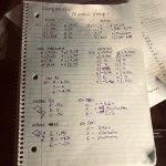
Finally have some normal voltages going all led’s working and I feel I’m very very close would someone mind looking at these voltages while I audio probe this? Cause I still have no effect .will I get no signal on the output until the trimmers are dialed in?
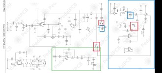
Ok So I've got signal all the to one side of R14 Checked and have continuity pad to pad and off board wiring all good yet no signal at the out pad. Granted a weak signal but getting a signal to 1 component going out I've checked all values everything seated voltages seem good can't get the signal off the board maybe time for a jumper ... ? see if I can get off the board I'm a bit confused with why this is happening it should be working
Well never mind previous post we had a friendly super small solder bridge now I have signal on the output
Solder bridge done. Boxed back up . cords plugged in power on and beautiful fantastic no tick dead nut silent fanfriggentastic THANK YOU PEDALPCB what an amazing pedal playing with the trimmers is a blast It would cool having a couple of these but each set up uniquely Not a really tough build its just all the usual stuff good soldering if you use sockets make sure your parts are seated in well getting full contact ( I had 2 recent ones that sprung to life when I had push quite a bit harder than normal to seat) also the dc supply keep it nice and short it did help to make the tick audible as I moved it around
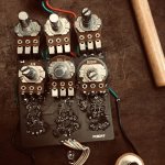
Trimmer adjustment
I did by ear each string back and forth until you hear a real nice blend. With micro adjustments you can hear the changes in the bounces or steps spend a little extra time with trimmers This build pissed me off a bit only cause it was hard to find my mistake(s). And they always always are. My mistakes have always been whats prevented a pedal from working right whatever it might be. Maybe 2 times something didn't work was from a faulty part out of hundreds of builds.
This pedal is well worth the effort