Making the "Ultimate" Prototyping Breadboard - A BtR Creation

BuddytheReow

Breadboard Baker
Hey Folks,

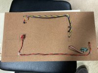
I'd rather just write my thoughts down than lose sleep over this. My original breadboard was 2 breadboards mounted on a few pieces of cardboard. Then a protoboard fell into my lap last year. An excellent upgrade indeed! The protoboard is great, but I think it needs some additional tasty goodies.

@fig was kind enough to give me a bench power supply to REALLY start tinkering with some circuit legos and unleash my inner mad scientist!

So....I think it's time to make my own "ultimate" protoboard. Don't get me wrong; I loooooove a good solder session! It's actually quite therapeutic for me to shut my brain off for a while and not think about the outside world. Here's what I'm thinking.

The protoboard uses 2 800-hole breadboards. I rarely use the second one for builds so I think this is a good amount or real estate. Any more and it's overkill and will take up too much space on my bench. I have to store it somewhere, ya know?

I need to connect the bench power supply to my board. But, I also need to have a DC power plug for a battery or to steal from my pedalboard's power supply if needed. I want it controlled with a switch and have a LED indicator to tell me which power supply I'm using.

Fig also sent me a digital voltage meter display. Here's an example of one:
https://www.amazon.com/gp/product/B079N98PY4/ref=ox_sc_act_title_2?smid=A30QSGOJR8LMXA&psc=1 I can use this to test voltages on certain components. I'd have to get a probe too and control it with a switch. Maybe later if I'm using just 9v input such as a battery I may want to utilize a charge pump or step down converter for other voltages.

Audio signal will be a separate section. I want a switch attached to an audio probe for further testing. Could I just use the output jumper? Sure, but I'm dreaming here and I want it!!! I would have to ground the enclosure to mount the in/out jacks.

I have some bluetooth chips. Should I make input/output bluetooth compatible? On the fence right now.

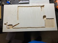
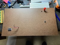
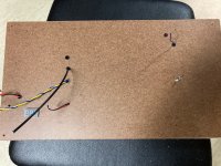
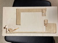
I don't have metalwork tools or experience, so this is going to be mounted on wood. Maybe not a single piece since I may need to hide some grounding wires/jumpers underneath, so I think I'll put a thin top. I may paint the darned thing once I'm done.

If anyone else has some ideas just let me know!

BuddytheReow
 
All of that....and more!

A protoboard and testing unit...

Add a built in wave generator...it's a stripboard circuit, or a breakout board already built.
Also, the bluetooth in can use phone apps for audio source...along with the 1/4" guitar input (of course).
The voltage display should be wired to the probe tip, and activated with a switch from audio to voltage...eh?
 
Last edited:
Oooh, I think a voltage "sag" control would be nice. Especially for fuzz circuits. I wonder how a muff would sound with lowered input voltage...:unsure:
 
  • Like
Reactions: fig
Interactive voice control. "Did you want me to make a cup of coffee while you test components?"
"Yes Kitt, don't forget the half and half this time"
 
I love my protoboard but I'd add:

a 2-color LED, on when powered, and one color when in bypass and the other color when engaged.

I'd move tall components (like the fuse and capacitors) away from the jacks, so you can put your finger on the back of the jack when inserting the connector.

A couple of switches you can tap like you can pots.
 
I'm gonna do it!!!!!!!

So, I found some scrap wood that was in pretty good shape and cut it oversized at this point. I can always trim it down.

I've got an extra 1590BB that I'll use as the main enclosure. Within it, I'll have my guitar signal going in/out with a LED to show active or bypass. A separate switch to engage an audio probe. There will be two power inputs (switchable of course) of either my bench supply or DC plug (think battery here) with a LED indicator telling me which one is active. Another switch to turn power on/off to the main boards. I then had another idea to use the small volt meter display to show me how much voltage is going to my boards. It also serves 2 other purposes: it will let me know if power is on and to tell me that I may have a dying battery in my future. I don't use batteries a whole lot, but it's still pretty cool. My woodworking router was a good friend to get this done.

The stripboard breakout boards are an old creation I'll probably transfer over to this new project.

I've also got a binding post on the right hand side where I'll probably plug in an extra multimeter lead. The jumper going to the main box will go underneath the top sheet, so I'll need to use a router to make a channel going to the 1590BB.

I've also got another small breadboard power strip on the right to act as an alternate power source. So, if I've got only 9v plugged in and I want a second, alternate voltage source I can use it here. I need to pull the trigger on a buck DC converter and also build a charge pump

1670537418807.png

1670537436909.png
 
Alright. Further testing is required.

Since I have a bench power supply that can go up to ~30V, I want to make sure that I can light up a diode and not burn it out. A simple 4.7k CLR as protection confirms that I'm good. I've also read that while this may be ok for now, the LED might burn out due to getting too hot. So, I left the power on for 10-15min just to make sure. I'd rather sacrifice a red LED before I get some Bi/Tri-Colored LEDs from Tayda and have a goof.

@fig also sent me a voltage step down module which will take any (I'm limited by my bench supply) voltage and reduce it. I was toying with the idea of just wiring up a potentiometer to act as a voltage divider, but for some reason my volt meter display gauge (not my multimeter) doesn't like that. So, solder a couple of +- wires to the in and out. There's a little screw on it to act as the pot which is kind of annoying, but I can work around it. It works! But, is it accurate? A simple check with the multimeter confirms it is pretty accurate to within 0.02V, so I'll take that.

This was a successful experiment. So far so good....
1670596707588.png
 
You could ditch the buck converter, and add a breakout board with a 3.3v linear VR, and a charge pump with -9vdc, and 18vdc to have on tap apart from the Main PSU.

I was thinking for probing circuits, I'd wire the test probe as such with a switch to be able to quickly check audio or voltage. Forgive my crude circuit drawing. 🤣

Screen Shot 2022-12-09 at 10.29.39 AM.png
 
Last edited:
Ok. So, before I go any further on this I took some time to lay things out on my Mega-Bread (the name will come to me at the most inconvenient time) just so I can see what I'm working with here. The bare board seemed a little big, but once I start populating it with some goodies...

Anyways, here's where I stand.

On the left is my main box. It will have 2 separate power sources: one for bench supply and one for a 9v battery or plug in power supply. The LED bezel sitting on the left will tell me which power supply is active and going to the breadboard. Those 2 stomp switches are placeholders until I get some 3pdt toggles from Tayda hopefully next week. The top one is to switch between the power supplies. The bottom one is for active/bypass of the guitar signal. The other pole on that switch goes to a LED to tell me which is engaged (thinking a Red/Greeen LED here). There are 2 other dpdt switches. These will engage the audio probe (the banana plug terminal you see toward the top right) and engage the LED right next to it. The other switch toward the top of the box will simply turn the power on/off to the breadboards. Those red and black speaker terminals at the top are just placeholders until I get smaller ones from Tayda.

9v battery to the right of the box that I will need to put a DC plug on it. Below the box is a banana plug will represent a terminal for ground only. I figured if I have to check voltages I can just pull out the DMM, throw the black lead in there, and test away. Also some extra space at the bottom for some tweezers (more handy than you think when breadboarding).

In the middle starting at the top is an older stripboard build with terminal blocks for pots and some dpdt switches. Switches are a PITA on a breadboard, so they'll be externally mounted. Below that are 2 main 800 hold breadboards. Below that is another terminal block stripboard build for pots and a rotary switch mod board (half of it is cut off in the pic but it has a knob on it) from GuitarPCB.

Back to the top again, but this time more to the right is a terminal for a multimeter probe to act as the audio probe with a LED bezel right next to it to tell me if it's on or not. That will be wired to the 1590BB. Right below that is a dip socket for the output signal where I simply throw the breadboard jumper in there. I'm a little hesitant about using it since it may wear out after a few uses, but we'll see. What do you think? :unsure: Right below that is an alternate breadboard power strip for my second voltage if needed. Below that is the good 'ol pink styrofoam from Tayda where my other voltage meter will be mounted.

To the right of the power strip is a DPDT that will throw the original power supply to either a stripboard build charge pump (still need to test it for 9v, -9v,18v, maybe 25v on a breadboard before I build it) or the buck converter. The buck converter will give me nearly any voltage below the original voltage. I think it stops at 1.5v? I should probably check that, but the volt meter needs a minimum of 4v to activate. This will act as a sag control and give me some other voltages. I know a PT2399 needs 5v. To adjust the buck converter I need a small screwdriver, so I will mount a cable tack upside down to hold it. Those things always disappear.

The top right corner I will leave blank for other goodies, such as my TC-1 tester or transistor sub box you see below.

So, I think that's it? Dang, this it turning out to be more complicated that I'd like. But, I accept the challenge!!!!

Thoughts and comments appreciated.

BuddytheReow

1670597876777.png
 
You could ditch the buck converter, and add a breakout board with a 3.3v linear VR, and a charge pump with -9vdc, and 18vdc to have on tap apart from the Main PSU.

I was thinking for probing circuits, I'd wire the test probe as such with a switch to be able to quickly check audio or voltage. Forgive my crude circuit drawing. 🤣

View attachment 37713
This is what I really wanted, but the volt meter display doesn't measure well when resistors are thrown into the mix. I think I'll just use my DMM.
 
Working from home on Friday's allows me to dip out for a few minutes and get something done around the house. At work I just check this place out and wander around youtube for a bit. I took 10-15 min in my woodworking shop, aka garage, to mount the top panel, make both boards flush with each other, and took a router to round off the bottom edge so I can grab it easier. The pic doeesn't show it very well, but it's there. Maybe at the end of this project I'll throw some rubber feet underneath. Who knows? I may take some time on my lunch break today and prime the enclosure. Warmer days are fast drawing to a close for rattle cans.

1670606388449.png
1670606416542.png
 
Lunch break today I primed the enclosure. Just need to pick a color out of my rattle cans. Also took a drill and router for the channels. It doesn’t look the prettiest since I did I freehand, but, like a stripboard build as long as it works who cares what it looks like underneath.
 

Attachments

  • 5329B3AE-9A66-4691-954C-E8EED1A91878.jpeg
    5329B3AE-9A66-4691-954C-E8EED1A91878.jpeg
    225.5 KB · Views: 8
  • 21BD68B6-0C12-4818-AAC3-971D3185AB48.jpeg
    21BD68B6-0C12-4818-AAC3-971D3185AB48.jpeg
    441.3 KB · Views: 8
Still waiting on my Tayda order to come in hopefully next week, but I can still chip away at this. I used my router to clean up the channels, make them bigger, and neater. An edge guide really helps here. I also took the afternoon to wire up some things like the second power supply, the regular signal output, and the audio probe diode. The regular output wire is shielded cable which I have like 15 feet so I might as well use it. I also had a bag of LED bezels which I don’t really like to use on my pedals since they don’t look very good. I used those on the hardboard to make where the cables come out a bit cleaner. Than the wiring itself. I had to go back and forth to my garage and route out the channels just a touch more each time. A hot glue gun tacks down the wires pretty nicely.

Not bad considering I’m doing this project on the fly. I do enjoy the problem solving part quite a bit.
 

Attachments

  • CC9CB249-A036-4E3A-B42A-1303923F624F.jpeg
    CC9CB249-A036-4E3A-B42A-1303923F624F.jpeg
    505.4 KB · Views: 8
  • C60F494C-6D91-4E36-8D14-2D53833E29A6.jpeg
    C60F494C-6D91-4E36-8D14-2D53833E29A6.jpeg
    271.1 KB · Views: 8
  • 5B2F9841-5B86-46F1-8FEE-BD51D7C1CFD6.jpeg
    5B2F9841-5B86-46F1-8FEE-BD51D7C1CFD6.jpeg
    544.6 KB · Views: 8
I also tried out a hammered finish rattle can. Looks pretty good. This will be the main enclosure.
 

Attachments

  • D03C00DA-4665-4918-85A4-53D621798B02.jpeg
    D03C00DA-4665-4918-85A4-53D621798B02.jpeg
    247.4 KB · Views: 19
Back
Top