MKI Tone Bender

JamieJ

Well-known member
The one has been on the breadboard for a while (the micro protoboard has been massively helpful). I tried out about 20 transistors for Q1 and finally settled on one. It sounds pretty awesome. I have never played a real or clone of a TB so who knows if it sounds anywhere near what it should but it sounds great none the less. I need to try it out with my whole board at a decent volume. From my first impressions, I prefer this to my Twin Face build.

I used the original as the inspiration for this one. I left out the LED as the original doesn't have one.
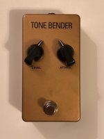
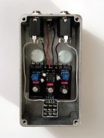
image0-1.jpeg

image6.jpeg
 
I’m planning on a MK I as well. I have some germanium transistors in my Small Bear cart.

I’m going to do another board design for the MK I/Zonk.
I absolutely love Doyle Bramhall and wanted to build a zonk machine but it wasn’t in stock so I built a MKI instead.
 
I absolutely love Doyle Bramhall and wanted to build a zonk machine but it wasn’t in stock so I built a MKI instead.

Technically, the Zonk! is a MK I. There's only a single component difference between the two and you could have tacked that on no problem.
 
Nice build, I like the color... Can you share what you used for transistors in each spot? (Gain and leakage numbers please)
 
Nice job. Very Old School sound.

For anyone considering building this, it's easy to ditch the charge pump and build an NPN version if you are so inclined. They used PNP back in the day because the best transistors were PNP. No so any more. I built one using Russian NPNs.
 
@danfrank from memory -
Q1 - Gain 109 Leakage 290
Q2 - Gain 80 Leakage 70
Q3 - Gain 89 Leakage 220

I tried to get Q1E and Q3C between -3v and -6v. With the attack pot at 0 Q2C should be around -9v. The pot fully CW will be 0v and the sweet spot for me is about 10 o’clock. I think I got this from @Chuck D. Bones somewhere on here.

My memory for specifics is poor but I think it was helpful to bias Q1 with R1 as a 1M trimmer. I also put R7 as a 20k trimmer.

It is definitely a good circuit to breadboard first before commit it to a PCB. This circuit definitely needs tweaking. I also find it’s very responsive to my tone pot on the guitar.
I build my first with PnP and a PCB. Not perfect, but definitely in the ballpark. Like Chuck Bones, I did another with NPN, on a breadboard. Sounds more like a MK1 than the PNP version…though it’s still on a breadboard. Maybe I’ll just stick it in an enclosure…
 
Back
Top