Muzzle/zuul mod to (Muzzle+/Zuul+) possible?

JCE

New member
Hi,

I am curious. Has anyone modded the Muzzle to the Zuul+ recent upgrades, adding a hold and release? I looked up a suggested schematic on the (THAT gate chips) site to make such a gate but am confused on how to execute. I figured it would be as easy as adding a potentiometer in place of a resistor but I think there is more to it. Can anyone shed some light on the situation or guide me to some information that will help me learn? Thank you.
 
In addition to your questions, I'm curious if anyone has done this to their Muzzle/Zuul builds? The Lone Wolf mods of replacing the range switch with a pot, and the 10k at the input with another pot.

 
In addition to your questions, I'm curious if anyone has done this to their Muzzle/Zuul builds? The Lone Wolf mods of replacing the range switch with a pot, and the 10k at the input with another pot.

Thank you!!! This is some great info and a good start. I plan to test that Lone Wolf schematic out on my second Muzzle I just got asap. I will post my results here when done.
 
In addition to your questions, I'm curious if anyone has done this to their Muzzle/Zuul builds? The Lone Wolf mods of replacing the range switch with a pot, and the 10k at the input with another pot.

As much as I can't stand this wolf guy, these mods really take the muzzle to a new level. I just tested it and I'm very pleased with the results. I still can't get past the fact that he straight up changed two fixed resistors to potentiometers and has the nerve to call it his own. I didn't really need any more reasons to dislike him, but this kind of stuff just confirms my feelings towards him. Then again, I read somewhere the Zuul design was completely stolen as well from the noise gate in the Marshall jcm800kk.
 
In today's world there really aren't original designs for circuits. Everything's a copy of something else with a few tweaks
Yeah, I know but his whole attitude is pretty despicable. He acts like invented the wheel when in reality most of his stuff is just tiny mods of other pedals on PCBs that were clearly designed with auto-router. He treats his customers like garbage and honestly, I think he seems to have some kind of inferiority complex. I've never seen someone so hell-bent on trying to convince people that he and his pedals are better than "the competition." If he didn't act and market his stuff like a 10-year-old bully who thinks he craps gold, I wouldn't care.
 
It took some digging to find this, but for anyone that is interested in seeing what I'm talking about with the Zuul being based on the gate in the Kerry King JCM800, here you go. Take a look a the EQ file specifcally.
 

Attachments

  • 2203KK_eq.pdf
    124.7 KB · Views: 80
  • 2203kk_pre_pa.pdf
    142 KB · Views: 41
It took some digging to find this, but for anyone that is interested in seeing what I'm talking about with the Zuul being based on the gate in the Kerry King JCM800, here you go. Take a look a the EQ file specifcally.
This is new info to me. Thank you. 100% feel you on Lone Wolf Audio. Some youtuber had made a video about him and his character flaws recently. Long story short, Karma is real. Anyways, Thanks again
 
Can someone clarify that if these mods to be done on a regular muzzle kit? And how exatcly you'd do them? I'm a total noob, so I don't have a clue if they can be done or not. :D
 
Last edited:
Can someone clarify that if these mods to be done on a regular muzzle kit? And how exatcly you'd do them? I'm a total noob, so I don't have a clue if they can be done or not. :D
I will build my pedal that I bought soon and will let you know. I have tomorrow off so maybe I can bang it out then and verify for ya. I'll keep you posted.
 
Ok, so I did the mod. I cannot tell what the shift mod is doing. Im no expert myself so maybe im wiring it wrong. The Range mod on the other hand is working. It fine tunes the threshold from what I can tell.

Looking at the bottom of the potentiometer from left to right the lugs read 3, 2, 1. I wired the R10 "Range mod" spot with lugs 2 and 3 on the left side and lug 1 on the right.

Same thing for R7 "the shift" mod.

Maybe someone else can chime in to verify if I did this correct and what the shift pot should be doing. I have another Muzzle built by Gup-Tech. It has a different "THAT" gate chip in it, but from what I can tell works similar.
Ok, good to hear. How exactly did you wire the range mod? taking out the internal switch and wiring a pot there? Any suggestion on pot values?

The shift mode should be a sort of Hold -function, meaning that it controls how long the gate stays open.
 
Last edited:
* note: I confused the two mod sections above in the last comment. R7 resistor location is the Range mod area. * And you just need to wire the middle and outside lug. You can pick whatever outside lug you want, lugs 1 or 3.

As far as schematic information is concerned, potentiometer lugs, when looking at the bottom, aka with the shaft pointing away from you, reads from left to right 3, 2, 1. Now, you can pick whatever outside lug you want, lugs 1 or 3. This will change the resistance when you turn the knob from "0" to "10k" or "10k" to "0". Like a tone knob going from bass to treble or treble to bass. Like a gain knob going from clean to distortion or from distortion to clean. Its going to achieve the goal either way. Its a personal preference which outer lug you pick.

1. Make an account here: (An absolute wealth of information)

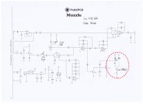
2. Download this schematic which shows mod locations:
3. Open the Muzzle guide document for R7, R10, and C6 and other references:
*Range Mod directions:


Looking at the Muzzle Pcb board you will see "3" electrolytic capacitors on the right side of the chips (that, 1054, tl072). The first resistor location "R7" above the "C6", this is the "Range Mod" section where you wire the b10k potentiometer. You will find out where R6 and C7 is from the Muzzle document on Page 1.

Example: (Looking at the Muzzle silkscreen aka component location side) find R7. left hole> 0-----[ R7 ]-----0 <right hole

1. Wire lug 2 from the B10k potentiometer to the left hole.

2. Wire lug 1 or 3 from same potentiometer the right hole.

*Shift Mod directions:

Follow the same directions for the R10 location as you did for R7. Using another b10k potentiometer.

*Notes:

The switch for the Muzzle's range section is still in its location. I did not alter or mod anything in this area. This switch turns on or off the "Range MOD" potentiometer now.


It is going to take time to learn this stuff. I have over 20 pedals or so under my belt and 1 amplifier. So although I know some things, I still have a lot to learn about how these components function in certain situations.

This mod is in working order but I may be missing something and it might not be working as good as it could or should. I can't emphasize enough to read up on this subject. I was told this early on and didn't want to hear it. I just wanted the quick and easy answer.

The more I learn the more grateful I am. The more I understand the easier it is to troubleshoot problems when putting a pedal together. I have bought a rack unit and a guitar pedal off ebay both broken/as is and was able to fix them!!!

Pedalpcb.com and Freestomboxes.org and Madbeanpedals.com forums have a lot of information but maybe grab a book or two as well to have help in the journey.

Goodluck.
 
Thanks! I understood it now. But how about this area in the schematic? I see the range & shift mods in place, but what does this one do?
 

Attachments

  • LWA_endless_blockade_sd-1.jpg
    LWA_endless_blockade_sd-1.jpg
    1 MB · Views: 54
Good on you for looking at that part. Not sure why it was necessary say it was not fitted though because.... drumroll....

That is your Led. The resistors above are to adjust its brightness. It is telling you when it is open or not on the outside of your pedal enclosure. It is a common cathode dual color led.... I think.

check this out and dig further... : https://1.bp.blogspot.com/-vJysJXCD...2R-sOs/w1937/Electrical-Schematic-Symbols.png

See if you can find it.
So that part is purely for aesthetics only? Then it's unnecassary for me, think the original led is good.
 
Back
Top