No Effect When Engaged - BYOC Tremolo Kit

PangeaDestructor

Active member
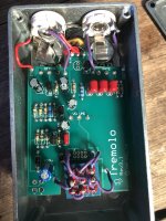
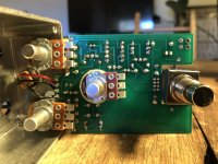
Hey All, first post here so apologies if I'm breaking any kind of rule or etiquette. I finally got this together last night, it's my second non-working attempt. The schematic is on page 25 at http://byocelectronics.com/treminstructions.pdf. Signal goes through the pedal fine when it's switched off. When I switch it on, it still goes through clean. No effect at all. The volume pot on the pedal works fine, but the rate and depth ones do nothing whatsoever.

I checked every resistor with a MM before installing them. I'm waiting on the parts for a probe so I can try and isolate the problemn (I have no idea how to actually do that yet, especially if one of the pots is the issue), but if anything looks obvious I'd appreciate some pointers. I'm not super proud of the mess I made, but the fact that it at least allows a signal through in both switch positions means something is right and it can be fixed, hopefully. Thanks!
 

Attachments

  • IMG_2049.jpg
    IMG_2049.jpg
    1.8 MB · Views: 13
  • IMG_2050.jpg
    IMG_2050.jpg
    1.1 MB · Views: 12
Are lugs #2 and #9 of the 3DPT bridged?

View attachment 10112
They are. I actually soldered in the LED because I was worried it might be a power supply issue, plugged it in, and no LED light. I pulled the DC input jack entirely off the circuit and plugged it in on its own. There's a ground and two positives. When I touch the black MM probe to the ground, I get just under 9v on one of the two + prongs. On the other, I get 0.00. The zero prong is slightly loose. Could the jack just be defective?
 
The 3rd lug of the DC jack is to switch from the internal battery to external PSU when a phono is plugged into the jack...or something like that...[insert standard disclaimer]
 
It sounds like your LFO isn't working as far as I know the LED forms part of the LFO circuit with Q4 the 1u caps rate pot etc so it needs to be installed looking at the schematic it'd be an open circuit going to Q4 collector without it

The LED should oscillate in time with the rate pot check what voltages you get on the LED pads

Q4 collector voltage should also vary with the rate pot
 
Last edited:
  • Like
Reactions: fig
I did a similar [EA type] build, and the rate adjustment was extremely sensitive (about 15% of the wiper sweep). Outside of that it would saturate and recovery was quite a wait. You definitely need the LED, just to find the sweet spot on the rate pot.

@Mcknib can definitely get you pointed the right way!
 
check the wiring connections on your footswitch

pin numbers when looking from the top:

123
456
789

the schematic shows pin 9 connects to pin 2, and pin 2 connects also to the PCB
your picture looks like pin 2 might also connect to pin 5 (maybe shorted by touching the wire that goes from pin 5 to the board)

make sure there is no contact at the footswitch between pin 2 and pin 5
 
  • Like
Reactions: fig
I actually got this figured out last night! First, the pics in their instructions were slightly off and I miswired lugs 1 and 5. Lug 8 on the switch was not getting voltage and I had the dc jack wired wrong. Switched those two red wires, replaced the faulty switch connection, wiped down the underside with alcohol, and it came right on with the flashing LED and everything.

Thanks to everyone for your help, on to the next one!
 
Last edited:
Back
Top