SOLVED Nobleman Overdrive Oscillation

Iceman53

Member
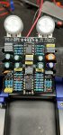
I am troubleshooting a Nobleman OD build for a friend

Symptoms:
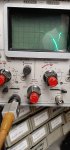
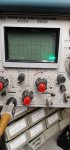
The pedal seems to work OK until the gain pot is increased. Once the pot's value is increased past about 32k, the circuit starts to oscillate. Backing the pot off stops the oscillation. Through an amp, it sounds like a motorboat. This occurs with no input (guitar), and with the input grounded. The oscillation signal starts out as sine wave then increases to a .6 v p-p square wave (with the corners smoothed off) riding on top of a 4.46 vdc level, at an 85 ms period.

What I tried:
I check component values in the feedback circuit, and a few near that circuit. I cannot find any wrong values. I am not sure what all of the components in the feedback loop are supposed to be doing. I'm guessing there has to be oscillation protection built in somewhere. I tried a different op amp. Same symptoms.

Any ideas or suggestions are appreciated
 
Can we get a picture?
Where you are probing, IC1 pin 1?
Have you verified that all of the correct components were installed? In particular, check R7, R9 and C101.
Take a look at the signal on Vref, let's see if the oscillation is coupling thru there. The signal will be small, if it's there.
 
Yes, probing IC1 pin 1
R7, R9 and C101 are all correct values
When the oscillation occurs, Vref has the same frequency signal, but very low, as you said. I put a 100uf cap in parallel with C101 and I am able to take the gain pot higher before the oscillation starts.
Scoped waveform attached. Horizontal sweep is 10ms/div
 

Attachments

  • 20200107_152138.jpg
    20200107_152138.jpg
    1,005.2 KB · Views: 18
Measure the resistance of R9 in-circuit (power off). There might be a short on the board. I can't find anywhere in the circuit that could force signal onto Vref other than thru D3 / D4.

Nice vintage scope. My Tek 465 is broken :(. Now I use a LabNation USB scope.
 
When you added the 100uF in parallel with C101, it lowered the oscillation freq, yes?

The signal is larger on IC1 pin 7 than pin 1, right?

With LEVEL cranked, it's about the same amplitude on IC2 pin 7 as IC1 pin 7?
 
With the 2 caps in parallel, the oscillation frequency is about 60 msec, as opposed to around 85 msec
IC1 Pin 7 is maybe 50mv larger than IC1 pin 1
With level cranked, IC2 pin 7 is much higher than IC1 pin 7. It is about 6v p-p. Attached pic
 

Attachments

  • 2nd pic.jpg
    2nd pic.jpg
    992.1 KB · Views: 10
One of the other guys puts an additional 47uF cap on the Vref line later in the circuit to battle oscillations. (Same circuit, different layout)

Might be worth a shot. (Positive lead goes to red circle, negative to blue)


PCB.jpg
 
The 3rd-stage (IC2.1) gain at 17Hz is around 3x. I would not expect to see 6Vp-p on IC2 pin 1 or pin 7. The trace looks like it's going off the screen on the bottom. At the top it's saturating the opamp.

It should not matter where along the Vref trace the additional cap is located.

The problem may be related to the power supply, it has happened to me before.
Can you see oscillation on Vcc? If so, is it larger or smaller than the oscillation on Vref?
What are you using to power this pedal?

If that line of inquiry doesn't bear any fruit, try this: jumper IC1 pin 5 to ground so as to temporarily kill the signal there. Do you still get oscillation at IC1 pin 1? I'm trying to figure out if the unwanted feedback loop is at the 1st stage or somewhere else.
 
Adding another 47uf cap on Vref made no difference.

PS is an Acopian 9GT100D-12GT100D. Good for 1 amp. It is dead clean at any setting on the pedal.

Jumpering IC1 pin 5 to ground results in no oscillations on IC1 pin 1.
 
Good clue!
Lift the IC1 pin 5 jumper and ground IC2 pin 3. Oscillations on IC1 pin 1?
Lift the IC2 pin 3 jumper and ground IC2 pin 5. Oscillations on IC1 pin 1?

I asked about the power supply because I was using a Monoprice 9V wall wart on my test bench. Those suckers are unstable and like to motorboat into light loads. I chased an oscillation in a pedal for the better part of a day before figuring out it was the power supply.
 
Lift the IC1 pin 5 jumper and ground IC2 pin 3. Oscillations on IC1 pin 1? No. 5.16 volts
Lift the IC2 pin 3 jumper and ground IC2 pin 5. Oscillations on IC1 pin 1? No. 4.24 volts

After step 1, I assumed you wanted me to replace IC1 pin 5 back in the socket before doing step 2

I knew why you asked about the PS. Been there. I only use regulated supplies.
 
Update - there is a 10uf cap installed in C18 instead of a 1uf. Not sure if I have one here. If not, I'll have to get one from the builder of the pedal. I will report back whenever I get that changed.
Thank you so much for the help!
 
Lift the IC1 pin 5 jumper and ground IC2 pin 3. Oscillations on IC1 pin 1? No. 5.16 volts
Lift the IC2 pin 3 jumper and ground IC2 pin 5. Oscillations on IC1 pin 1? No. 4.24 volts

After step 1, I assumed you wanted me to replace IC1 pin 5 back in the socket before doing step 2

There was no need to pull the IC lead out of the socket. These are input pins and it's ok if the output saturates during these experiments.
 
Update - there is a 10uf cap installed in C18 instead of a 1uf. Not sure if I have one here. If not, I'll have to get one from the builder of the pedal. I will report back whenever I get that changed.
Thank you so much for the help!

That would explain the larger signal at IC2 pins 1 & 7. I don't think it would cause the motorboating.
 
Back
Top