
You are using an out of date browser. It may not display this or other websites correctly.
You should upgrade or use an alternative browser.
You should upgrade or use an alternative browser.
Noisy Pauper
- Thread starter ericrudd
- Start date
ericrudd
Member
Made some progress, I guess. Switched the leads on the jacks and now it passes audio. All knobs affect sound. Not much “overdrive” to speak of. Tone control works. Internal treble pot works. External Three way switch does nothing, I don’t hear it “clicking” or any evidence it’s trying to affect the sound. Nor does the internal dip switches. I guess the next thing I need to verify is that I bought the right on/off/on switch.
ericrudd
Member
I’m very new to this. So any additional troubleshooting ideas would be greatly appreciated. I’ve been looking at the schematic and have been checking continuity with the IC and the various resistors and other points. I believe I put the chip itself in oriented correctly.
Hmm. For the toggle switch, did you happen to get a monetary switch by chance? (Which returns to the middle after you switch it, so it doesn’t stay switched).
If you got the right one (stays in the switches position) check for continuity between your components in that area in the different switches positions. it *seems like*, from your description, maybe those diodes aren’t getting activated.
If you got the right one (stays in the switches position) check for continuity between your components in that area in the different switches positions. it *seems like*, from your description, maybe those diodes aren’t getting activated.
Nostradoomus
Well-known member
Try sanding away the paint (down to bare metal) where the jacks mount. This will ensure a good solid ground connection
Are you getting a big volume boost? It’s sometimes helpful to report the voltage at each pin of the IC (which you have in the right way), and we can say if they look good.
I’m thinking...
-Big volume boost but light distortion means the diodes somehow aren’t getting activated.
-not much volume boost means some other problem with the amplification part of the circuit.
I’m thinking...
-Big volume boost but light distortion means the diodes somehow aren’t getting activated.
-not much volume boost means some other problem with the amplification part of the circuit.
ericrudd
Member
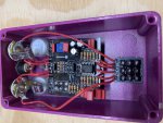
Here is the solder side. Sorry for the tone control being in the way. (Do I need to pull it for y’all to see?)
Phi1, I am getting a healthy swing of level in both the drive and level pots, and a healthy swing of tone variance with that knob. It kinda acts like a boost pedal with very little “crunch.” I have an ODR1 here I’m using as a comparison.

I’ll wire the power jack back on and measure the IC voltages. (I’ll google how to do that).
Thanks as always. And don’t laugh at my soldering job. ?
Phi1, I am getting a healthy swing of level in both the drive and level pots, and a healthy swing of tone variance with that knob. It kinda acts like a boost pedal with very little “crunch.” I have an ODR1 here I’m using as a comparison.
I’ll wire the power jack back on and measure the IC voltages. (I’ll google how to do that).
Thanks as always. And don’t laugh at my soldering job. ?
Last edited:
ericrudd
Member
Some more notes. Looking at the printed side of the PCB, here are some continuity notes for the MA856 diodes:
with the mini switch thrown in the up direction, the left lower two pins toned with the top leg of D3 and D1. The lower right two pins toned with the top leg of D2 and D4
with the mini switch thrown down, the top left pins toned with D3 and D1, and the top right pins toned with D2 and D4.

with the mini switch thrown in the up direction, the left lower two pins toned with the top leg of D3 and D1. The lower right two pins toned with the top leg of D2 and D4
with the mini switch thrown down, the top left pins toned with D3 and D1, and the top right pins toned with D2 and D4.
Just swing the Tone pot up towards the Footswiitch & take a Pic of that area.Here is the solder side. Sorry for the tone control being in the way. (Do I need to pull it for y’all to see?)
Phi1, I am getting a healthy swing of level in both the drive and level pots, and a healthy swing of tone variance with that knob. It kinda acts like a boost pedal with very little “crunch.” I have an ODR1 here I’m using as a comparison.
View attachment 4294
I’ll wire the power jack back on and measure the IC voltages. (I’ll google how to do that).
Thanks as always.
It really needs Cleaning with Isopryl & a toothbrush or Electrical cleaner!
All those voltages look good except I would expect pin3 to also be close to 4.5v (though I could be wrong). If it’s wrong I’m not sure shat could be causing that. I *think* your switch-diode connections make sense, without having thought too much about it

Similar threads
- Replies
- 7
- Views
- 295
- Replies
- 4
- Views
- 402