Ocelot Octave: No Sound

I just finished building an Ocelot Octave and there is no sound coming from the effect. The bypass works great and the LED comes on when pressed but that's about as far as I get.

On this pedal, the build does call for 1/4w resistors instead of 1/8w resistors... would this make that much of a difference if I mixed and matched? I can try to say which ones are 1/8w if you want but if it doesn't matter than I won't bother.

My other question, I think I installed the TL072 IC's correctly but since they don't have a notch, I am unsure. I do get 9v when I test what should be pin 4 and 8 but that might not mean much.

I am not sure where to go next... Oh, and almost ALL Vref points are ~5v. I checked all of the VCC too and they show ~9v. I am stumped here but this is my first time troubleshooting a pedal that wouldn't work.
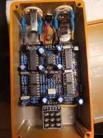
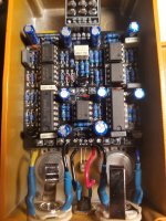
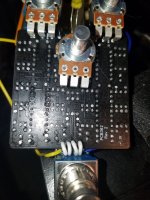
Ocelot_2.jpg Ocelot_4.jpg
 
Here is the backside for reference... I am completely dumbfounded as to what is wrong. I found out I did install the IC's correctly...

I will try to get voltage readings of some major components and post those later. Does using 1/8w resistors instead of 1/4w resistors make any difference? My thought is no, but that is the only thing I used that was different than the build document parts list.

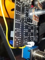
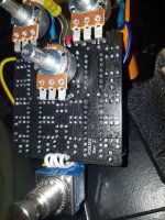
Ocelot Back_1.jpg
Ocelot Back _3.jpg Ocelot Back_2.jpg
 
1/8W resistors are fine. Your TL072's look to be installed correctly, the dot in the corner indicates pin 1 when there is no notch.

You mentioned measuring 9V on pin 4 of the TL072s, can you double check that measurement? You should have 0V (ground) on pin 4.
 
I was testing them weirdly last night... but with my multimeter grounded to the case of the pedal, pin 4 shows 0v on all TL072's. Not sure if it matters, but it looks like all the TL072 ar TL072CP... I got them from Tayda.
 
If you have no clean signal with the Direct pot turned up then you can eliminate a majority of the circuit as the problem. The octave shifted signals depend on the clean signal.

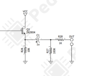
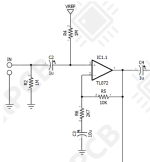
Assuming all component values are correct, no Direct signal would be a problem around IC1.1 (R2, R4, R5, R6, C2, C3) the Direct pot, or the Q1 output stage (R26, R27, R28, C1). You can, for now, ignore the rest of the circuit in between until you get a clean signal.
 
Here's a possible point of concern: IC5 only reads ~3v on pin 1 where all of the other TL072 read ~5v on pin 1.

Pins 2 & 3 all read ~5v on the TL072's.

Also on IC5, Pin 7 reads about 6v. Pins 5 & 6 on IC1 - 5 all read ~ 5v and Pin 7 of IC1 - 4 reads ~5v.

Pin 8 on IC1 - 5 reads the intended ~9v.
 
just for something easy to do -- try swapping around your TL072 ICs to different sockets to see if it makes any difference. not impossible you have a bad one, and it is easy enough to check. you can also measure the voltages at the sockets when the ICs are removed to see if that changes any of your readings.
 
Okay, for IC5, here are the readings WITHOUT the IC in the socket:

Pin 1: ~5v
Pin 2: ~5v
Pin 3: ~5v
Pin 4: 0v
Pin 5: ~5v
Pin 6: ~5v
Pin 7: Variable voltage from 4v - 6v
Pin 8: ~9v

Here are the readings when I swap IC1 and IC5:

IC1IC5
Pin 1: ~5vPin 1: ~3v
Pin 2: ~5vPin 2: ~5v
Pin 3: 4.4/4.5vPin 3: ~5v
Pin 4: 0vPin 4: 0v
Pin 5: ~5vPin 5: ~5v
Pin 6: ~5vPin 6: ~5v
Pin 7: ~5vPin 7: ~3v
Pin 8: ~9vPin 8: ~9v

Also, I just replaced R2 with a fresh 1M resistor because it was only reading 0.1 Ohm on the MM and now the LED wont come on. The LED was coming on before mind you... here is another weird oddity: when the switch was in the "off" position, I could press down on the 3PDT board/switch and the LED would kinda light up, but this is probably due to voltage/current running through my finger. Just thought I would note it though in case it matters.
 
use your dmm to check your footswitch the middle row should connect to the row closer to the PCB in one position, and then the outside row in the other.
 
If you have no clean signal with the Direct pot turned up then you can eliminate a majority of the circuit as the problem. The octave shifted signals depend on the clean signal.

Assuming all component values are correct, no Direct signal would be a problem around IC1.1 (R2, R4, R5, R6, C2, C3) the Direct pot, or the Q1 output stage (R26, R27, R28, C1). You can, for now, ignore the rest of the circuit in between until you get a clean signal.
Alright, I replaced R2 with a new 1M Ohm resistor but R26 has a 1M Ohm Resistor in it... what exactly is this specific resistor used for? Would either a 5.6k Ohm resistor or 22k Ohm resistor work in this spot? That is all I have on hand at the moment. I will order 10k Ohm if needed.
 
your quickest diagnostic tool now would be an audio probe. you can hunt down where the audio signal stops on the board.

^ This. Audio Probe is the next step.

You checked that the bypass is working, which is good, but now you need to demonstrate to us that signal is making it from your footswitch breakout PCB, to the main PCB, to the first active component of the circuit.

Start with Pin 3 of IC1 and work backwards.

1649788527809.png
 
Back
Top