
You are using an out of date browser. It may not display this or other websites correctly.
You should upgrade or use an alternative browser.
You should upgrade or use an alternative browser.
Paragon Mod
- Thread starter Travis
- Start date
Travis
Active member
So I must take out TC1044, D14 and D15 and jump d14 and d15.You have 9v at the output (cathode) of D7, and 18v at the output (cathode) of D15.
If you want to keep 9v only, don't solder the TC1044, and jump D14 and D15
Nice, Thanks
So I must take out TC1044, D14 and D15 and jump d14 and d15.
Nice, Thanks
Yes, you can also take out C21 and C22. And I would replace C10 with a 100u, for better filtering
Travis
Active member
First of all, thank you very much helping me, I will try all you said.Yes, you can also take out C21 and C22. And I would replace C10 with a 100u, for better filtering
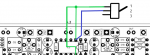
Just I thought this must works, if I remove 1 and 8 from PCB and get together in a wire (green) and then the blue wire I connect lug 2 of the switch to pad 1 of the PCB maybe it´s works and it´s more simple, dont you think?
Thank you again.
Attachments
Travis
Active member
Ok Thanks !!!No, this is not gonna work. Or actually it might, but it seems a bit odd to me!
But again, 18v isn't very interesting in my opinion with this circuit.
The benefit of a pedalpcb board is that it is very neat to assemble, with the pots and switches mounted on the circuit board. That usually means these boards are not easy to modify to bring in new functions or options. you can substitute parts but not easily add in extra things. If you are not a skilled builder I would suggest building the board as called for, or at most swapping out existing parts with different values. Sometimes even getting something like you are suggesting "sort-of working" will still leave you with a project that is unreliable or too noisy for you to enjoy using it.
There are other projects you can build if you want a swtichable power supply to use with other pedals that can work at dual voltages. Like this: https://edfedtalent.ibc.doi.gov/mod/scorm/player.php
There are other projects you can build if you want a swtichable power supply to use with other pedals that can work at dual voltages. Like this: https://edfedtalent.ibc.doi.gov/mod/scorm/player.php
Travis
Active member
Thanks you tooThe benefit of a pedalpcb board is that it is very neat to assemble, with the pots and switches mounted on the circuit board. That usually means these boards are not easy to modify to bring in new functions or options. you can substitute parts but not easily add in extra things. If you are not a skilled builder I would suggest building the board as called for, or at most swapping out existing parts with different values. Sometimes even getting something like you are suggesting "sort-of working" will still leave you with a project that is unreliable or too noisy for you to enjoy using it.
There are other projects you can build if you want a swtichable power supply to use with other pedals that can work at dual voltages. Like this: https://edfedtalent.ibc.doi.gov/mod/scorm/player.php
Yes, I was able to add a 9v/18v switch to this circuit without too much trouble. The only additional part is a DPDT On-On switch. I removed diodes D7 and D15 from the board and soldered them directly to the switch as shown. I soldered D14 to the board but elevated it slightly so that I could solder a jumper wire directly to its cathode lead. In 9v mode, the switch essentially bypasses the TC1044, directly connecting the 9v source to the op amps and voltage divider. In 18v mode, the switch recreates the circuit as shown in the schematic.
Also, I find that I prefer the sound of this circuit in 18v mode.
Also, I find that I prefer the sound of this circuit in 18v mode.
Attachments
Travis
Active member
I ask and if I do this wiring the green wire to IC and the blue one to PCB (taking out 1 and 8 from PCB) must work.First of all, thank you very much helping me, I will try all you said.
Just I thought this must works, if I remove 1 and 8 from PCB and get together in a wire (green) and then the blue wire I connect lug 2 of the switch to pad 1 of the PCB maybe it´s works and it´s more simple, dont you think?
Thank you again.
uranium_jones
Well-known member
Just a heads up... I tried this mod, and for some reason, when I switch from 18V to 9V, capacitor C10 starts to smoke. (double checked the polarity and the power rating.)Yes, I was able to add a 9v/18v switch to this circuit without too much trouble. The only additional part is a DPDT On-On switch. I removed diodes D7 and D15 from the board and soldered them directly to the switch as shown. I soldered D14 to the board but elevated it slightly so that I could solder a jumper wire directly to its cathode lead. In 9v mode, the switch essentially bypasses the TC1044, directly connecting the 9v source to the op amps and voltage divider. In 18v mode, the switch recreates the circuit as shown in the schematic.
Also, I find that I prefer the sound of this circuit in 18v mode.
Lol! I'm not laughing at you, I just think smoke is funny...
Easiest way to convert the Paragon to 9 volts is just to remove the charge pump (TC1044) from the PCB.
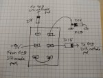
If you want it voltage selectable, that will be a little harder... Lift up the cathode of diode D15 off of the PCB, see attached picture where the ball point pen is pointing to. Get a SPDT (on-on) toggle switch, see pic #2. Use a wire to attach the cathode lead of D15 to the left terminal of the switch. The PCB "hole" where D15 cathode used to be soldered to will go to the middle terminal of the switch. The right terminal of the switch will go to the positive lead of the DC power connector. Hope this helps.


Easiest way to convert the Paragon to 9 volts is just to remove the charge pump (TC1044) from the PCB.
If you want it voltage selectable, that will be a little harder... Lift up the cathode of diode D15 off of the PCB, see attached picture where the ball point pen is pointing to. Get a SPDT (on-on) toggle switch, see pic #2. Use a wire to attach the cathode lead of D15 to the left terminal of the switch. The PCB "hole" where D15 cathode used to be soldered to will go to the middle terminal of the switch. The right terminal of the switch will go to the positive lead of the DC power connector. Hope this helps.
Travis
Active member
I did that on my ones and it's worksI ask and if I do this wiring the green wire to IC and the blue one to PCB (taking out 1 and 8 from PCB) must work.
Sorry to hear about the smoke Quality_Jones. This switch mod is designed to completely bypass the charge pump in 9v mode. I can report that I've used the switch mod I described above for over a year without any problems. Again, in 9v mode, it simply connects the 9v from the D7 anode directly to the anode of D15, effectively removing the charge pump from the circuit. Looking at other KOT schematics (and assuming they're correct), the 9v mode here recreates the original KOT circuit. In 18v mode, the circuit is exactly as shown in the Paragon schematic.
DanFrank's switch mod should work as well and is a little simpler. However, it looks like the charge pump would still be connected to power in this configuration (the DPDT switch mod I described disconnects the charge pump from the power supply). Not a problem, but it might drain a battery slightly faster. I might suggest connecting D15 to the middle lug of the switch instead, with the anode soldered to the lug and the cathode soldered to D15's cathode pad on the pcb. Then solder a wire from D15's anode pad to the switch's left lug and connect the 9v supply to the right lug as originally described. This would then allow D15 to be present in 9v mode as well and is probably closer to the original KOT circuit.
Here's a photo of the DPDT switch in my Paragon for reference. Happy to help with any debugging for anyone who wants to give the DPTD mod a try.

And here's the finished product:

I should mention that the Paragon has been my main overdrive pedal for the past year. I love how it sounds and it gets a lot of use. I should also mention that, for all the trouble of implementing the 18v/9v switch, I far prefer the 18v setting.
DanFrank's switch mod should work as well and is a little simpler. However, it looks like the charge pump would still be connected to power in this configuration (the DPDT switch mod I described disconnects the charge pump from the power supply). Not a problem, but it might drain a battery slightly faster. I might suggest connecting D15 to the middle lug of the switch instead, with the anode soldered to the lug and the cathode soldered to D15's cathode pad on the pcb. Then solder a wire from D15's anode pad to the switch's left lug and connect the 9v supply to the right lug as originally described. This would then allow D15 to be present in 9v mode as well and is probably closer to the original KOT circuit.
Here's a photo of the DPDT switch in my Paragon for reference. Happy to help with any debugging for anyone who wants to give the DPTD mod a try.
And here's the finished product:
I should mention that the Paragon has been my main overdrive pedal for the past year. I love how it sounds and it gets a lot of use. I should also mention that, for all the trouble of implementing the 18v/9v switch, I far prefer the 18v setting.
Similar threads
- Replies
- 2
- Views
- 100
- Replies
- 1
- Views
- 122
- Replies
- 3
- Views
- 153