SOLVED Paragon Whistle/Scream

piapium

Active member
Unfortunately another pedal hasn’t worked at first try again.

1st channel engaged:
tone pot is full -> whistle

2nd channel engaged:
tone pot is full -> whistle

Both channels engaged -> whistle on any position of the pots.

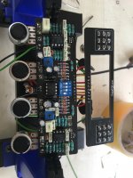
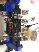
Will upload pictures and a video tomorrow.

Appreciate any help. Thanks!
 
Last edited:
Reflowed all the solder joints. Tried different tc1044scpa. Both channels work if I don’t turn up the pots noon. When I turn them up whistle. Everything is in the correct position and soldered the correct parts. Don’t know what else to do. What can I check using dmm. It’s frustrating but an experience.
 
Last edited:
At a quick glance everything seems correct, need to look at resistors a little harder though. Can you clean the rosin flux off the board with alcohol and a toothbrush, it makes it hard to see solder joints with it on. And have you tried adjusting the presence trim pots, they are tied to the tone stack.
 
I cleaned and reflowed all of them, there were some cold joints, fixed them. Before reflowing channels also weren’t working separately. Now they are working one by one. Messed with trim pots too. When both channels on it screams after turning the pots past noon. And thanks for answering.
 
Just finished looking at resistors, they are all correct as far as I can tell. To make things easier, the 4 dip switches that control the clipping, make sure all 4 are off. This way there is no distortion to troubleshoot for now. Also, can you take the voltage measurements of each pin of the IC chips, lets see what they are doing. And you are welcome.
 
2IC1

Pin 1 9,18

Pin 2 9,20

Pin 3 4,54

Pin 4 Ground

Pin 5 8,92

Pin 6 16,23

Pin 7 9,12

Pin 8 18,22


IC2

Pin 1 9,20

Pin 2 9,21

Pin 3 4,58

Pin 4 Ground

Pin 5 8,91

Pin 6 14,44

Pin 7 9,11

Pin 8 18,21


IC3

Pin 1 9,93

Pin 2 6,24

Pin 3 Ground

Pin 4 -3,18

Pin 5 -3,15

Pin 6 5,10

Pin 7 4,24

Pin 8 9,92


Diodes

From positive to negative


1 13,80 - 11,51

2 9,09 – 13,80

3 11,54 – 8,73

4 8,71 – 9,09

5 8,90 – 9,80

6 9,08 – 8,90

7 9,92 – 9,80

8 13,75 – 11,79

9 9,10 – 13,73

10 11,78 – 8,72

11 8,72 – 9,09

12 8,90 – 9,08

13 9,08 – 8,90

14 15,33 – 9,92

15 18,20 – 15,33
 
Unfortunately another pedal hasn’t worked at first try again.

1st channel engaged:
tone pot is full -> whistle

2nd channel engaged:
tone pot is full -> whistle

Both channels engaged -> whistle on any position of the pots.

Will upload pictures and a video tomorrow.

Appreciate any help. Thanks!
90% TC1044

Try to remove it and use the pedal in 9 volts.
 
I removed the tc1044 and it works to a point. when i dime all the pots it whistles again. but if dime all of them and turn the tone knob ccw a little it stops whistling. but using both channels it whistles whatever the position of the knobs.
 
On the pots, leg 2 is the variable leg, resistance between 2 and 3 will change as you rotate the pot. What's baffling is the op amp voltages. Are you sure they are right. Pins 2 and 3 should be close but you have 9.2 and 4.5 volts on both IC1 and IC2. On IC1 pins 5 & 6 you have 8.9 and 16.2 volts, on IC2 you have 8.9 and 14.4 volts. In an op amp circuit with feedback, the op amp will drive output voltage to try and get both input pins to be equal, so pin 2 and 3 should be close and pins 5 and 6 should be close. So I took a closer look at your picture, don't know if it will help but check IC2 to ensure it is fully inserted, it looks like bottom of op amp isn't fully inserted. Then recheck the IC1 and IC2 voltages
 
I wiggled them and 5&6 readings are now around 9 for both op amps. But 2&3 still has difference like 4 to 9. A100k pots has 25k ohms at noon. They are 0 at both sides. And right tone pot has no reading when both channels engaged. Left is ok. But get no reading also on gain volume pots when both channels are on only left tone pot has normal values.
 
An A100K pot will read about 25K at the noon position, the taper on an "A" pot is logarithmic. Look up logarithmic pot taper and you should see a graph of the resistance curve. The 4 and 9 volts is what's bothering me. Remove IC1 and measure pin 3, it should read about 9 V with the IC removed. Pins 1 and 2 should have 0 on it with IC removed. If its not 9 V on pin 3 then remove IC2 also and check pin 3.
 
Back
Top