Pauper pooper

Mike McLane

Active member
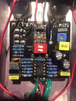
Building my second Pauper. First one went fine. Just completed the second one and volume, gain, tone and toggle all seem be doing what they're supposed to do RELATIVELY speaking, however, the unit only puts out about half the gain and volume of my real Prince of Tone. The first Pauper basically stood toe-to-toe with the real deal. I double checked the component values and all seem to be correct (I checked them all with a meter before installation). I included a gut shot in case anything look suspicious. Any advice would be helpful.
 

Attachments

  • Pauper.JPG
    Pauper.JPG
    74.8 KB · Views: 60
Hmmm? No love in PedalPCB land? I remelted any suspicious solder joints, particularly the IC socket. Tried two different IC's. . . no change. Volume, Gain & Tone all modulate the signal, however, I'm thinking that the Vol & Tone are 100% and Gain is wimping out. Was hoping to get some suggestions on voltages to test at various critical points in the circuit. Also, I'd been on the wait list which suggests this was a brand new production run. . . maybe someone else is experiencing same issue.
 
First voltages to take are the power supply voltage. At the cathode of D5 you should have about +9V. At the junction of R12 and R13 you should have around +4.5V. If these are good, take voltages on all legs of op amp referenced to ground. Once you have these post them in the thread.
 
Values to Ground:
Power supply = 9.38
Cathode D5 = 9.21
Junction R12 & R13 = 4.6
IC 1 = 4.68
IC2 = 4.69
IC3 = 4.27
IC4 = 0
IC5 = 4.61
IC6 = 4.61
IC7 = 4.59
IC8 = 9.21
 
Quick idiosyncrasy check, the treble trimmer is part of a passive tone stack, are they set the same ? Passive tone stacks are volume droppers in general and removing treble will sound like a lower volume. Also ensure the dip switches inside pedal are set the same. Both of these can affect volume.
 
Last edited:
Also verify C2 is a 100pF cap, looks a little big but it could be a higher voltage than I am used to seeing, which is no issue as long as its 100pF.

And if you could, take another picture of the volume and drive pot from the front side. From the one picture pin one and three of the volume pot looks like its not soldered or possibly a cold joint.
 
Last edited:
Tone seems good. . . ran it thru full range and does what you'd suspect. It and P.O.T. were both set the same, moved dips back and forth and didn't hear much if any change in tone or gain in Pauper. . . also checked it with meter to make sure it functioned as intended. C2 is stamped "101J" so it should be a 100p/5%. A pic of the Vol and Gain solder joints is attached. [DUMBSHIT ALERT] Looks a little messy, but that's cause I absent mindedly soldered the pots in "upside down" and had to pull them out and replace them. I removed the old pots by bending them back and forth until the legs broke loose then removed the legs one at a time from the PCB and sucked the solder clean. Could there be damage to the PCB as a result of the change that would result in partial functioning? Its getting late here so I can remelt the solder joints on the pots tomorrow and see if that improves things. Thx loads for your help!
 

Attachments

  • Pauper.JPG
    Pauper.JPG
    108.7 KB · Views: 36
Most likely no damage occurred if you broke the pots legs fist. I have done similar thing and broke out the big snips to cut the legs, then remove them. Its the easiest way with a pot. If you damaged the pad/hole you would know it, no sound would come out.

This is a much better angle. The pots could use a little more solder on them and pin 2 of the volume looks like a cold joint. Add a little more solder to them and see if it helps. If not you may have to probe the circuit to see if/where the volume drop is occurring. If everything checks out, it may just be that tis is where the pedal operates. I have seen that on occasions. I built 2 identical OD1's and one was noticeably louder than the other. Everything was installed and working correctly on both, that's just where the pedal was at.
 
Yeah, noticed the IC and seated it properly. . . did not change performance. Since Vol & Tone seem to be OK I thought last night about 1 or 3 being bad on the Gain pot. I was getting "something" out of the Gain and it modulated the signal, but it was extremely "punky" and since either side of the Gain pot had a "path" of some sort to the Output I thought that might provide a "one-sided" signal response (am I showing my ignorance here :cautious:
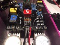
). Anyhoo, I tested the continuity from the pins on the Gain pot to the next component in the schematic and it checked out OK so I didn't break any traces in the PCB relative to the Gain mounting holes. I'll reheat the pot joints and see what we get.
 
Well friends and neighbors, reworked the pots. . . no change in performance. This thing is simply missing Gain. Spent some time A/B'ing with POT and with POT Gain @ min and Pauper Gain @ max they sound almost identical. . . both had Volume max'd and they produce similar volumes. I started scoping the Gain pot and came up with the attachment that completely perplexes me. Per schematic Terminal 3 is wired directly to R16 and Terminal 1 is wired directly to R3. . . then no resistance btw these pairs of points, right? . . . and when full CW, resistance T2-T3 is 93K and T2-T1 is 0. At that point T3-R16 should be 0 and T2-R16 should be 93K shouldn't it? Nope, I get 93K & 0 respectively (just the opposite). . . . T1-R3 should be 0 and T2-R3 should be 0, but I'm getting 93K on both?!?!? How 'bout that sports fans!?!?! I understand that there could be interactivity coming from other parts of the circuit, but don't understand how I could get a 93K reading when the schematic says that there is a direct connection btw two points void of any component. Could there be something going on here or is my "epidermis" (i.e. stupidity) showing (sorry, old joke)? img20201201_14330619.jpg
 
T2 connects to one side of R16 and T3 connects to the other side. When Fully CCW T1 to T3 should be about 50K. When fully CW T1 to T3 should 100K. Check it that way.
 
I get 93K (100K) both directions. If you are right then I would wonder if there's something wrong with the PCB b/c the pot works as it should (I tested it a several points in the wiper rotation) and I can't see how the pot in and of itself could account for those readings. I checked the continuity from T2-R16 (good), C2-R16 (good), C2-IC2 (good), R3-R4 (good) . . . just checking connections in the neighborhood to see if anything appears to indicate a broken trace.
 
I do believe you have the pot legs numbered backwards. If looking at component side of board, from left to right it would be 3-2-1. Your diagram shows 1-2-3. Pauper.png
 
Last edited:
Yep, right again. Drats! Still getting 93K both directions, though. There comes a time when you just gotta say, "WTF!" The amount of time we (more correctly, YOU) spent on trying to debug this guy you reach a point where you're better off to cut 'er loose and start over with a new PCB. One final thought, when testing continuity I noticed that C2 (even though its labeled 101J) returned a value of around 400p. Also, I got some "real" MA856's from Pedal Hacker. Could they be bogus and, if so, be a problem source. Can I test diodes with a multi-meter to see if they're in spec?
 
Some multimeter have a diode checking function on them that will tell you the forward bias voltage, that's all you can really check. The spec sheet for the MA856 says the forward voltage is 1Vdc max. So Really no way to tell if they are fake or not. I doubt they are fake, pedal hackers has good stuff and cater to builders like the guys on this forum, so....

C2 has some crazy parallel paths in this circuit, these will change the reading of the cap if measurement is take from components already mounted to board. The only way to get the 100p is to remove it. But since its a strange value, it is most likely good, you are seeing the other paths, mainly the op amp.
 
A couple of things you can to, if you haven't done so already change out the op amp. If no change, use an audio probe. Start at the beginning of the circuit and work your way through and see if there is indeed a sound drop in the circuit. Check before and after each component from left to right on the top run of the schematic. when doing this turn the drive pot up a little over half way so you know that you have gain after IC1.1and switch the DIP switches, when checking IC1.2 toggle the switch in each position to ensure you here a change. If you have a drop while doing this, then concentrate on that portion of circuit. If you have gain throughout the circuit then that's the way this pedal likes to operate.
 
Back
Top