MichaelW
Well-known member
This was one of the boards in the most excellent grab bag of goodies that @DGWVI sent me recently.
PCBGuitarMania has a bit of a less than stellar reputation around here (with good cause).....my own experience with their projects hasn't been great but wasn't anything as catastrophic as some other members have experienced.
But @DGWVI assured me that the ones he sent me all checked out and he had built them all. So putting aside my bias I got excited about building some of these out. First up is the Submarine Device. Basically their version of the PedalPCB Abyss, otherwise known as the EQD Depths.
It's an optical vibe pedal and a super simple one.
I've been toying on and off with the idea of building the ElectroVibe (Shin Ei's take on the Univibe) but every time I looked at the build docs it gave me a headache. There's a crap ton of components on it, and lots of mod threads, and tweaks and biasing tricks and it just hasn't been worth for me to attempt it for a sound a rarely use.
I had a retail Deja Vibe for a while that sounded really good, but after I ran out Robin Trower licks to play it kinda just sat on the shelf gathering dust until I finally sold it. Yet, everyone once I a while I still think I'd like a Univibe sound. So this project was the PERFECT answer, I didn't have to decide hahahaha.
Anyway, the EQD Depths is a optical vibe and their take on the classic Univibe circuit. It's a lot less complex than the ElectroVibe with a lot less parts.
I think it gets you about 95% of the way there to a Univibe with a lot less work and a lot less components.
The PCBGM version was well laid out and a really good project. No goofy wrong build components and misinformation or anything like that.
It's got one little tweak to it in the form of a mod to allow you to put in a toggle to control a bi-color LED to get some different sounds as an option.
I decided to skip that mod and just jumpered the toggle and built it to EQD specs with a yellow LED. @DGWVI even sent me some PCBGM 3dpt boards to go with the boards he sent me so offboard wiring was a cinch. The only substitution I made was using GL5528's instead of the recommended KE-10720's.
I have just enough KE-10720's to build out my Duo-Phase and didn't want to place yet another Tayda order just for LDR's. So I decided to take the chance that the GL5228's were close enough. And they certainly are! the pedal sounds GREAT!
Since the DC in and Ground jacks were exact opposites of PPCB boards I decided to be cute and invert the DC jack from my normal build practice (Positive to the west and ground to the east). So inverting them allowed me to have straight runs from the board to the jacks with buss wire.
Then like an idiot, when I went to go ground the jacks I spaced out on autopilot and grounded them to the east DC lug....which was now positive.
So testing it at my bench obviously didn't work...until I finally figured that out. Then I melted the DC jack getting the wires off it so I said screw it, took the board out and replaced the jack. Once correctly wired it fired tight up. As I said, it sounds really great. But as I was reviewing the build docs he mentioned experimenting with the distance between LDR and LED and getting different sounds. So I opened it back up and adjusted the LDR's to about 2mm from the LED. That one little thing has given the pedal a LOT more effect and richness. Pretty cool! The LDRs are now actually a lot closer than in the pick below.
As per the build doc's you can use a 2mm guitar pick to set the distance. (I don't have any 2mm pick so I just eyeballed it... )
)
Anyway, easy build, went real quick, "relatively" low parts count for a Vibe and sounds awesome. Very glad to have this sound back in my stable.
Thanks again @DGWVI! I'm probably going to be building one of the other PCBGM boards you sent next.
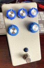
I used the "stone texture" Rattle can again. I think I have a few more enclosures worth in this can, Interesting paint. I kinda like it, but after 3 pedals I'm also kinda sick of it too....heh.

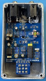
The LDR's are now much closer to the LED's now than in this picture. Little tiny moves in the distance of the LED to LDR can make a pretty big difference in how much effect you get. Also there is a "Throb" control that controls low end pulse. According to EQD it "comes alive with a neck pickup and some dirt". I've found this to be very true. It's a much more effective parameter using the neck pickup than bridge and more pronounced with some gain than it is clean.

PCBGuitarMania has a bit of a less than stellar reputation around here (with good cause).....my own experience with their projects hasn't been great but wasn't anything as catastrophic as some other members have experienced.
But @DGWVI assured me that the ones he sent me all checked out and he had built them all. So putting aside my bias I got excited about building some of these out. First up is the Submarine Device. Basically their version of the PedalPCB Abyss, otherwise known as the EQD Depths.
It's an optical vibe pedal and a super simple one.
I've been toying on and off with the idea of building the ElectroVibe (Shin Ei's take on the Univibe) but every time I looked at the build docs it gave me a headache. There's a crap ton of components on it, and lots of mod threads, and tweaks and biasing tricks and it just hasn't been worth for me to attempt it for a sound a rarely use.
I had a retail Deja Vibe for a while that sounded really good, but after I ran out Robin Trower licks to play it kinda just sat on the shelf gathering dust until I finally sold it. Yet, everyone once I a while I still think I'd like a Univibe sound. So this project was the PERFECT answer, I didn't have to decide hahahaha.
Anyway, the EQD Depths is a optical vibe and their take on the classic Univibe circuit. It's a lot less complex than the ElectroVibe with a lot less parts.
I think it gets you about 95% of the way there to a Univibe with a lot less work and a lot less components.
The PCBGM version was well laid out and a really good project. No goofy wrong build components and misinformation or anything like that.
It's got one little tweak to it in the form of a mod to allow you to put in a toggle to control a bi-color LED to get some different sounds as an option.
I decided to skip that mod and just jumpered the toggle and built it to EQD specs with a yellow LED. @DGWVI even sent me some PCBGM 3dpt boards to go with the boards he sent me so offboard wiring was a cinch. The only substitution I made was using GL5528's instead of the recommended KE-10720's.
I have just enough KE-10720's to build out my Duo-Phase and didn't want to place yet another Tayda order just for LDR's. So I decided to take the chance that the GL5228's were close enough. And they certainly are! the pedal sounds GREAT!
Since the DC in and Ground jacks were exact opposites of PPCB boards I decided to be cute and invert the DC jack from my normal build practice (Positive to the west and ground to the east). So inverting them allowed me to have straight runs from the board to the jacks with buss wire.
Then like an idiot, when I went to go ground the jacks I spaced out on autopilot and grounded them to the east DC lug....which was now positive.
So testing it at my bench obviously didn't work...until I finally figured that out. Then I melted the DC jack getting the wires off it so I said screw it, took the board out and replaced the jack. Once correctly wired it fired tight up. As I said, it sounds really great. But as I was reviewing the build docs he mentioned experimenting with the distance between LDR and LED and getting different sounds. So I opened it back up and adjusted the LDR's to about 2mm from the LED. That one little thing has given the pedal a LOT more effect and richness. Pretty cool! The LDRs are now actually a lot closer than in the pick below.
As per the build doc's you can use a 2mm guitar pick to set the distance. (I don't have any 2mm pick so I just eyeballed it...
Anyway, easy build, went real quick, "relatively" low parts count for a Vibe and sounds awesome. Very glad to have this sound back in my stable.
Thanks again @DGWVI! I'm probably going to be building one of the other PCBGM boards you sent next.
I used the "stone texture" Rattle can again. I think I have a few more enclosures worth in this can, Interesting paint. I kinda like it, but after 3 pedals I'm also kinda sick of it too....heh.

The LDR's are now much closer to the LED's now than in this picture. Little tiny moves in the distance of the LED to LDR can make a pretty big difference in how much effect you get. Also there is a "Throb" control that controls low end pulse. According to EQD it "comes alive with a neck pickup and some dirt". I've found this to be very true. It's a much more effective parameter using the neck pickup than bridge and more pronounced with some gain than it is clean.


