BuddytheReow
Breadboard Baker
This is a stupid simple build and IMO one of the most efficient mods given the number of parts this takes. This mod can be done on countless circuits, especially one-knob fuzz pedals. Some of my more recent posts have been talking about tone filters/controls. Here's an extract from one of them.

Low Pass Filter - anything below a certain frequency determined by the combination of values for the resistor and capacitor will go through the circuit.
High Pass Filter- anything above a certain frequency determined by the combination of values for the resistor and capacitor will go through the circuit.
Not that you know a little "theory" let's talk about the PedalBlock Tone Control. Here's the schematic and the build doc.

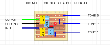
This is literally the Big Muff Pi tone control skeleton. Compare the two pictures above. Can you tell which is which in the schematic? C1/R2 form a high pass filter and R1/C2 form a low pass filter. The 'TONE' potentiometer merely blends the two together. Clockwise is more treble and CCW more bass.
Here is what it looks like on my breadboard. EDIT: I have tried to make my breadboard look as close to the schematic as possible. The white jumper on the left is my output. The yellow jumper (yes, it's yellow. My camera/lighting sucks) is on the right and my input.

2 things need to be mentioned about this:
1. It is a passive tone filter. It requires no power and dumps all the unwanted signal to ground. This means that it will suck out some noticeable volume. The simple fix is to put a booster circuit block after it as a recovery stage. If you've wandered around forums wondering what is a recovery stage, it's usually just a booster.
Edit: I would recommend starting here. https://forum.pedalpcb.com/threads/...toboard-start-here-lpb1-some-dirty-mods.8354/
2. Depending on the values you use for the components there will be an EQ notch. The original BMP had a noticeable mid scoop sound because of this tone stack. Google it if you're interested in looking at all the EQ curves to prove it.
Want a Civil War tone knob or Ram's Head? Check the build doc! Here are the values for the components. Of course, experiment with different values to find the tone "window" that you like.

BuddyTheReow
Low Pass Filter - anything below a certain frequency determined by the combination of values for the resistor and capacitor will go through the circuit.
High Pass Filter- anything above a certain frequency determined by the combination of values for the resistor and capacitor will go through the circuit.
Not that you know a little "theory" let's talk about the PedalBlock Tone Control. Here's the schematic and the build doc.
This is literally the Big Muff Pi tone control skeleton. Compare the two pictures above. Can you tell which is which in the schematic? C1/R2 form a high pass filter and R1/C2 form a low pass filter. The 'TONE' potentiometer merely blends the two together. Clockwise is more treble and CCW more bass.
Here is what it looks like on my breadboard. EDIT: I have tried to make my breadboard look as close to the schematic as possible. The white jumper on the left is my output. The yellow jumper (yes, it's yellow. My camera/lighting sucks) is on the right and my input.
2 things need to be mentioned about this:
1. It is a passive tone filter. It requires no power and dumps all the unwanted signal to ground. This means that it will suck out some noticeable volume. The simple fix is to put a booster circuit block after it as a recovery stage. If you've wandered around forums wondering what is a recovery stage, it's usually just a booster.
Edit: I would recommend starting here. https://forum.pedalpcb.com/threads/...toboard-start-here-lpb1-some-dirty-mods.8354/
2. Depending on the values you use for the components there will be an EQ notch. The original BMP had a noticeable mid scoop sound because of this tone stack. Google it if you're interested in looking at all the EQ curves to prove it.
Want a Civil War tone knob or Ram's Head? Check the build doc! Here are the values for the components. Of course, experiment with different values to find the tone "window" that you like.
BuddyTheReow
Last edited:


")