Phase II Problems

Jovi Bon Kenobi

Well-known member
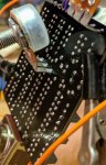
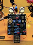
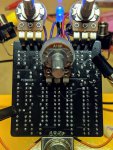
Finished building this up and it is not producing any effect when activated. When activated and the indicator LED is on I just get my dry guitar signal. There is a very faint ticking sound relative to the rate potentiometers position if it's on or off. As I do with every build, I audited every component for correct value before soldering. I recorded all the voltages on all IC's and the transistor with my DMM. I'll post them in a few minutes but here's the photos.

Oh, and the 2 things I did differently from the build doc is use a 5mm UV LED for the indicator (build doc says 3mm red, is that the fault?!) and also, I used an A50k for the rate because I don't have any A25K's.
 

Attachments

  • IMG_20190614_112550.jpg
    IMG_20190614_112550.jpg
    234.3 KB · Views: 67
  • IMG_20190614_112142.jpg
    IMG_20190614_112142.jpg
    451.3 KB · Views: 74
  • IMG_20190614_112341.jpg
    IMG_20190614_112341.jpg
    306.1 KB · Views: 67
Last edited:
Here are the voltages:

Voltage at DC jack: 8.7v

IC1:
1: 0.6mV 2: 0.9mV 3: 0.1mV 4: -7.39V 5: 0.1mV 6: 1.2mV 7: 1.3mV 8: 8.4V

IC2:
1: -6.7V 2: nothing 3: nothing 4: -7.39V 5: nothing 6: 2.5mV 7: 7.4mV 8: 8.4V

IC3:
1: 7.0mV 2: 3.2mV 3: nothing 4: -7.36V 5: nothing 6: 2.5mV 7: 4.4mV 8: 8.4V

IC4:
1: -0.5mV 2: -0.4mV 3: nothing 4: -7.35V 5: nothing 6: 4.9mV 7: 5.4mV 8: 8.4V

IC5:
1: 7.9V varies with depth/rate 2: -0.8mV varies with depth/rate 3: varies with depth/rate 4: -7.36V 5: nothing 6: 4.2mV 7: 6.0mV 8: 8.4V

IC6:
1: varies with depth/rate 2: nothing 3: varies with depth/rate 4: -7.37V 5: 0.1mV 6: 0.7mV 7: varies with depth/rate 8: 7.73V

IC7 (TC1044SCPA):
1: 8.4V 2: 5.06V 3: 0.5mV 4: -2.9V 5: -7.37V 6: 3.9V 7: 5.19V 8: 8.4V

Q1 (2N4401):
E: 7.6V varies with depth/rate B: 7.88V varies with depth/rate C: 8.4V
 
Last edited:
For now I would reflow your switch soldering, looks pretty iffy. Also it’s hard to see but the LED should be flat side up. I have working Phasor II and duo phase builds I can check voltages on when I get home later. ?
 
you can't get any phasing without a variable light source. you can play something through the pedal while shining a flashlight over the photoresistors if you want to see if the phasing circuit will respond.
 
Since swapping the polarity of the yellow LED it now lights up properly and adjusts like it should to the rate and depth pots, yet I still just get my regular guitar signal regardless of said LFO. No phaser sounds when engaged. I'm at work now for the next few hours but I'll be home after to troubleshoot more.
 
you should put together an audio probe to see if you can trace the sound as it goes through the parts of the phasing circuit. you can do a google search for some simple build instructions and how to use it.
 
Something is funky around your transistor, just measured mine (knobs set at zero) and I’m getting

C 8.8v
B 4.2
E 3.6v

Try reflowing your solder points on components surrounding it and anything relating to grounding. This problem sounds like a cold joint somewhere.
 
I appreciate everyone's help but I'm at a loss. I made an audio probe but I don't know enough about circuit order to properly use it. I reflowed a bunch of points around the PCB that looked spotty. I changed out all the socketed components for new ones. With the probe I was getting a sort of broken phaser sound on a couple of points, pin 6 of IC3, only one of the photoresistors legs, etc...

Sorry for your trouble.
 
no need to apologize to anyone for what you don't know about getting your pedal to work. you're doing about the best you can flying blind. but it is very tough to troubleshoot a circuit without being able to compare what you have on the board with how things are supposed to fit together on the circuit diagram.

as noted above, you should check connections of your parts to the PCB (and to each other as shown in the circuit board) around the transistor where Nostradoomus is getting different readings on his build of the pedal.

and track down a few more articles and watch some youtube videos on how to use the audio probe. do the same thing for looking up how to use your DMM. that material is there, and most us have had to plow through it one way or another along the way.
 
Oh yeah it’s no trouble. I love this stuff and am happy to help.

I’m still basically at the same spot you are, I can not follow a signal path with a probe to save my life. I do know that if you audited all of your components for faults beforehand and use decent quality parts, the most likely thing is a bad solder joint, switch, pots or something off board. I was recently tearing my hair out when every build I had in the pile didn’t work (weak unaffected signal etc)...it was the switch on my test box (which I cannot suggest as your next build enough!)

Put it aside and take on something easier, there’s no shame there. Good luck!
 
Maybe look at a working pedal you have built and the circuit diagram for it, and use your audio probe to learn how to follow the signal through it to get some practice. Then you will have more experience using it to find where something stops working when you are troubleshooting.
 
Back
Top