SOLVED Pro-10 Dual Overdrive issues

Jazzwolf

Member
Hello all,

I am a bit of a novice to the pedal making game. I have made 4 pedals from aion effects and those all turned out well. This is my first PedalPCB.com pedal and I am having some issues. The Blue side (Left when looking down at top) gives me no sound at all when activated. This is likely a beginner issue on my part.

Things that work:
  • I have sound in bypass
  • The "Green Side" works perfectly
  • Both LEDs work when the switch is pressed.
Things that don't work:
  • Blue side doesn't work at all when that side is switched on, no sound at all.
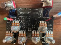
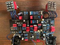
I looked for a schematic for this one and it's not posted yet. I have attached pictures of the top and bottom.

Ryan top.jpg bottom.jpg
 
Solution
OK, I got this bad boy working! Between R127 and pin 5 of IC100.2 there was no connection. I made a solder bridge between them (since the connections were super close physically) and it came back to life. Not sure how that connection broke, wonder if it was a board defect?

Thanks for the guidance!


Survivalist.jpg
That board has a whole lotta parts on it, so it's easy to get one or two in the wrong place. "Build Docs Coming Soon..." It's high-risk to build a board without the build docs. Clean all of the flux residue off of both sides of the boards using liberal amounts of alcohol & a toothbrush. Don't get any dirty solvent into the pots. Inspect the board using the pic of the PWB on the website as a reference.

WTF is that 150K monstrosity? Did you sub any other parts?
Thanks for the reply!

No subs. The 150k monstrosity is three resistors in series to equal 150k. I heatshrinked them after I soldered them end to end. I forgot the 150k when I ordered DOH! That thing is on the Green side (I think). I'll do a one by one check of the parts, focusing on the Blue side. I will also do a clean of the back side. I did a preliminary clean but as you can see it still needs work.

I likely shouldn't have picked this complex of a pedal yet but I love the Protein and wanted to try it out.
Ryan
 
Yeah, that's on the green side. I have schematics for the two separate Blue & Green boards. That 150K resistor could be 100K, 150K or 220K and it wouldn't matter.

Do you have a DMM? We can do a quick health check on the ICs.
 
Yeah, that's on the green side. I have schematics for the two separate Blue & Green boards. That 150K resistor could be 100K, 150K or 220K and it wouldn't matter.

Do you have a DMM? We can do a quick health check on the ICs.
Thanks for the reply.
Good to know on the 150k monster. I just got a real 150k resistor and am switching it out anyways.
As for the DMM, mine died today :(. I had a cheap one. I bought another so it should be here tomorrow.

I have spare ICs too we could switch out if these are bad.

Thanks!

Ryan
 
I'm out of pocket tomorrow.

Check pins 1 & 7 of the TL072, pin 6 of the TL071. They should all be near +4.5V. If one of them is wonky, that will narrow the search.

Changing the ICs will probably not help because at least 90% of the time, the problem is workmanship. Keep inspecting until you find the bad solder joint, wrong part or solder splash.

Good luck!
Thanks! I will check those out tomorrow.
 
I'm out of pocket tomorrow.

Check pins 1 & 7 of the TL072, pin 6 of the TL071. They should all be near +4.5V. If one of them is wonky, that will narrow the search.

Changing the ICs will probably not help because at least 90% of the time, the problem is workmanship. Keep inspecting until you find the bad solder joint, wrong part or solder splash.

Good luck!
So the TL072 is at 4.27v and the TL071 is at 4.2. Seems a tad low.

Thanks,

Ryan
 
Have you ohmed that footswitch on the blue side? there's an awful lot of solder on those lugs, you want to be sure nothing is shorting under the breakout board
Thanks for the reply. I haven't omhed anything yet. My new DMM had just come in so I could check that next. I will check back when I do that so we can start crossing stuff off. :)

Thanks!
 
I ohm'ed out everything and I am having some issues with my socket for the TL072. Pins 6 &7 have continuity. Back of the board looks fine, but i think i have a bridge under the socket most likely. I am working on pulling that. That would blow my op amp correct? I will pull that socket, clean it up and install a new socket carefully.

The rest of the circuited ohm'ed out perfectly.

Thanks,

Ryan
 
  • Like
Reactions: fig
I ohm'ed out everything and I am having some issues with my socket for the TL072. Pins 6 &7 have continuity. Back of the board looks fine, but i think i have a bridge under the socket most likely. I am working on pulling that. That would blow my op amp correct? I will pull that socket, clean it up and install a new socket carefully.

The rest of the circuited ohm'ed out perfectly.

Thanks,

Ryan
That shouldn’t blow the chip.
 
It would bridge CH 2 inverting IN to CH 2 OUT. I haven’t looked at the schematic but if CH 2 is on the Blue side, that would certainly seem the cause.
 
So the TL072 is at 4.27v and the TL071 is at 4.2. Seems a tad low.

Thanks,

Ryan
Those readings are close enough. Shorting pins 6 to 7 on the TL072 would kill the signal on the Blue side. It would not damage the opamp. When you get the socket out, you'll probably find a solder splash or a bit of conductive debris underneath.

I have the schematic and I gotta says that if this is an accurate trace, then the person who designed the Blue channel does not understand circuit design. Should it work as-designed? Yes. Does it contain a bunch of superfluous parts? Definitely. The Blue channel is a Blues Breaker with a 11.7dB boost at the end, hence the name. The Green channel is an ODR-1 with a slight reshaping of the bass response on the first stage. In case you were wondering, Nobels paints the ODR-1 green.
This is interesting, not that I understand circuit design, but definitely seems like there are an excessive number of components for an MBB on the blue side.
 
Back
Top