I just started build a Promethium today and have so far only populated the board with the resistors, the diodes and the IC sockets. I am about to install the 1µF caps C10 and C12 and the only caps of that value I have which will fit are tantalums. The board has no indication of polarity for these - what sort of 1µF caps am I supposed to use? There isn't the room for poly or electrolytic.
So I got my meter out to work out to check which ends to connect where according to the schematic only to discover I have no continuity between the IC's pin 7 and the pads for C10. I get continuity between pin 7 and D2 and if I look at the underside of the board I can see the PCB trace goes to the left-hand end of C10 and C9 but my meter gives me no signal at those points. The board looks fine and there's no way I burnt a trace or anything.
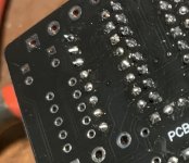
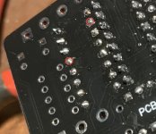
Then as I look on the back of the board at where R18 is soldered to the board I can see a tiny bit of copper poking through the black coating.
It's the fourth solder joint down on the left. Is that a piece of trace poking through?
So I got my meter out to work out to check which ends to connect where according to the schematic only to discover I have no continuity between the IC's pin 7 and the pads for C10. I get continuity between pin 7 and D2 and if I look at the underside of the board I can see the PCB trace goes to the left-hand end of C10 and C9 but my meter gives me no signal at those points. The board looks fine and there's no way I burnt a trace or anything.
Then as I look on the back of the board at where R18 is soldered to the board I can see a tiny bit of copper poking through the black coating.

It's the fourth solder joint down on the left. Is that a piece of trace poking through?


