Protoboard build and a couple of questions.

Fizz

Well-known member
Build Rating
5.00 star(s)
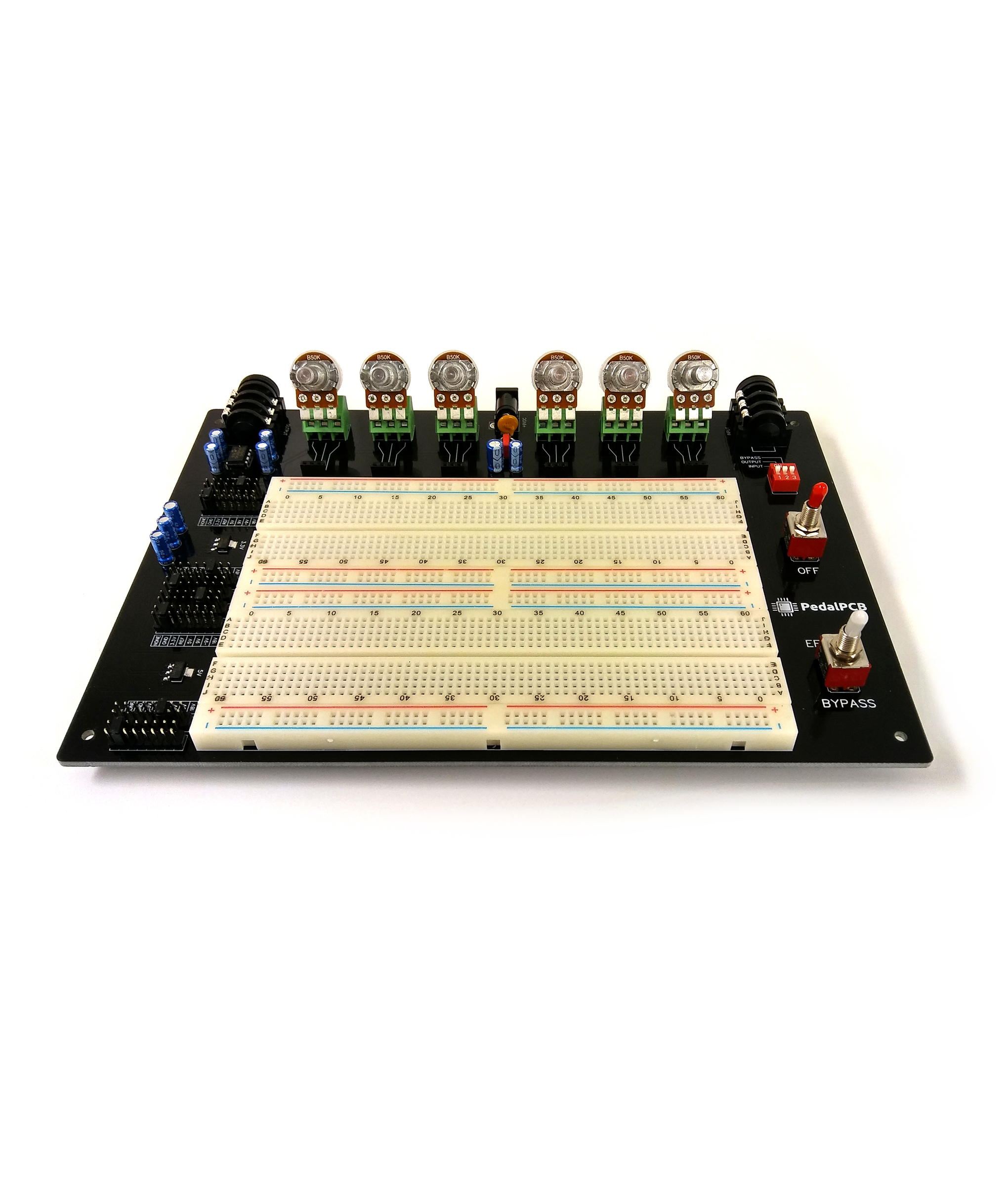
I built this one yesterday and it was an easy and fun build. Soldering all those pins was a great soldering exercise. So were the big lugs and holes that I don't usually see on PCB builds. I can't wait to start testing pedals on this.

I used the from AP1084D33G AP1084 LDO Voltage Regulator IC 3.3V 5A from Tayda and it was slightly too large but somehow I got it to work by adding a little more solder. I used the from LM1117 LM1117MPX 5.0V 800mA Low-Dropout Linear Voltage Regulator from Tayda and it was a perfect fit.

All my voltages on the pins tested perfect except the 18v was around 17.85 which is close enough.

I love that it has an on/off switch so I can test builds in line with others.

What is the Effects Bypass used for?

What is the best method to test PCB builds before I box them up.. how should I connect the breadboard wires to the PCB without soldering them?
 
Thanks... I just assumed the on/off simulated the footswitch but that makes sense now that you posted that.

If you power the circuit off without bypassing you'll just have silence, not a clean bypassed signal.

17.85V is pretty good for the 18V supply, it's generally not dead on 18V because of the forward voltage drop of the diodes in the charge pump circuit.
 
If you power the circuit off without bypassing you'll just have silence, not a clean bypassed signal.

17.85V is pretty good for the 18V supply, it's generally not dead on 18V because of the forward voltage drop of the diodes in the charge pump circuit.
That does make sense to me now and a great feature to test my builds with other pedals. I figured the 18V source was good but just wanted to make sure since the others were dead on.

This board is going to be such a useful tool for me.. Thanks for designing it and offering it for sale.
 
What did I connect wrong here? I put my terminal blocks in just like the picture below and am doing this easy LPB-1 boost to test out my Protoboard. My A100K pot is inserted just like the ones in the picture on the Protoboard. I figure 1,2,3 on the lugs in the way the pot is facing input, output and ground, left to right. So C2 is going into 1 on the left, 2 is going to my output pin on the Protoboard and 3 on the right is going to ground. But I have to turn it down to get volume and up to lower the volume. Turning left goes up and right goes down. What did I do wrong?

lpb-schematic.png
ProtoBoard.jpg
 
That's backwards. Pin 1 of the pot should go to ground, Pin 3 should go to C2.

As you turn down the pot the wiper moves closer to the pin to the left, which is ground, reducing the volume.
 
That's backwards. Pin 1 of the pot should go to ground, Pin 3 should go to C2.

As you turn down the pot the wiper moves closer to the pin to the left, which is ground, reducing the volume.
Thanks.. I don't know why this confuses me but I look up the pinouts online and think I understand but this schematic didn't list them as 1,2 and 3 like others do.

The new Multifunction tester I purchased this week sure is a big help though... especially with transistors

61gYQdfhmxL._SX466_.jpg
 
Back
Top