Question about reading Vero Layouts

Crash102

Well-known member
I have a questions about the Vero layouts. I understand what links are. And the how the components go. But for a few weeks I've been wondering what the heck the red squares mean. however, i think I've figured it out and want to double check. The image below says 3 links, 10 cuts. I put two and two together and think that "cuts' refer to the red squares. Is a cut simply removing the copper from that square so as to sequester off parts of the board? image_2023-01-05_173459353.png
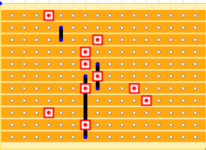
 
Those are cuts meaning you have to make holes there breaking the trace in that specific location. The idea is to not let continuity pass. Take a drill bit and start hand drilling thru the hole till the trace is broken. If you have a vero board that has eyelets like a normal circuit board or is double sided then make sure to do both sides. You can take your multimeter put it in continuity mode and check to see if there is still continuity or not. Hope that helps.
 
Last edited:
Those are cuts meaning you have to make holes there breaking the trace in that specific location. The idea is to not let continuity pass. Take a drill bit and start hand drilling thru the hole till the trace is broken. If you have a vero board that has eyelets like a normal circuit board or is double sided then make sure to do both sides. You can take your multimeter put it in continuity mode and check to see if there is still continuity or not. Hope that helps.
Thank you, that's what i was trying to convery what i thought they were. Thanks for mentioning the drill, I was wondering how to best go about it
 
"Hand drill" in the literal sense. Don't use a power tool or you'll easily go right through the substrate. Hold a drill bit with your fingers (I tend to use a 1/8" bit) and twist it back and forth until you can't see the copper strip anymore. It should also be mentioned that the layout is viewed with the copper side facing down. When you turn it over to make the cut you'll have to view it from a mirror image perspective. See that first cut on the top row in the 4th column? When you flip it over from left to right you'll have to make the cut on the top row 4th column from the  right. When you flip the Vero right side up your cut will match the layout. Check out Chucks Vero post in the boneyard for more tips.

Edit. I tend to like Vero over a PCB. I did a write up stripboard if you need some help.
 
Last edited:
I should've mentioned the mirrored part! Thats very important, use a sharpie to mark the hole on the other side so you dont get confused!
 
Ha! I use a cordless drill to make the cuts but use it slowly. I've got quite good at it now, 20 0000 boards made now!! 🤪

And if you're looking at the layout in Preview it's easy to use "flip horizontal" in tools to give you the mirror image. Then (on a Mac) hit Command-Z to turn it back again. On a PC it's probably similar but will make a chiming sound as you do it.
 
3mm bit perfect for vero. Just made a vero project last night. DIY layout creator, new version is great.
 
I have a questions about the Vero layouts. I understand what links are. And the how the components go. But for a few weeks I've been wondering what the heck the red squares mean. however, i think I've figured it out and want to double check. The image below says 3 links, 10 cuts. I put two and two together and think that "cuts' refer to the red squares. Is a cut simply removing the copper from that square so as to sequester off parts of the board? View attachment 39637
Everything you need to know about building Vero is in this tutorial, and in several others on the Tagboardeffects website - https://tagboardeffects.blogspot.com/2012/04/vero-build-guide.html?m=1
 
If you have a small battery drill (or even better, Dremel like rotary tool), using a small ball end burr to cut the traces always worked best for me. You don’t have to press very hard to “erase” the copper lines.
 
Cant wait to see what youre building ;)
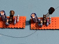
Nothing too serious this first go around. I'm wanting to splice in a couple of these Tillman's discrete Fet guitar preamps into an mxr bluebox clone that I'm working on. One going into the pcb and one going out. I figure it's an easy Fuzz that I'm working with. The perfect candidate to try something new for me. I'm Waiting for an order to put that last 10uf in but I think wiring them into the pcb will be harder than they were to build.

I've read that these can be wired in so that they're always on, but I want to hook it up so that they're only on when the effect is on, so it's back to studying and reading and trying to figure that part out. Think I'm going to have to diagram it in Microsoft paint just to wrap my head around it. D15DEDA2-B2E0-4981-8D66-5815DAF5ABE0.jpeg
 
Nothing too serious this first go around. I'm wanting to splice in a couple of these Tillman's discrete Fet guitar preamps into an mxr bluebox clone that I'm working on. One going into the pcb and one going out. I figure it's an easy Fuzz that I'm working with. The perfect candidate to try something new for me. I'm Waiting for an order to put that last 10uf in but I think wiring them into the pcb will be harder than they were to build.

I've read that these can be wired in so that they're always on, but I want to hook it up so that they're only on when the effect is on, so it's back to studying and reading and trying to figure that part out. Think I'm going to have to diagram it in Microsoft paint just to wrap my head around it.View attachment 39724
Right on! Looking good! Keep us updated!
 
... I want to hook it up so that they're only on when the effect is on, ...View attachment 39724

If you haven't already figured this out...

Only on when the Bluebox is on:
IN-JACK > BYPASS-IN > TILLMAN 1 > BLUEBOX > TILLMAN 2 > BYPASS-OUT > OUT-JACK


Always On Tillmans:
IN-JACK > TILLMAN 1 > BYPASS-IN > BLUEBOX > BYPASS-OUT > TILLMAN 2 > OUT-JACK


Do make a diagram, though, as that always seems to help me out, too.
 
Back
Top