RG Keen – Panning For Fun Question

benny_profane

Well-known member
I'm looking to adapt the RG Keen "Panning for Fun" circuit for a project. I had some questions about the first op-amp stage of the 'high-impedance' version.
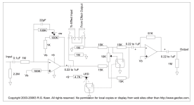
panning for fun.png

First, is the first op-amp being used as a differential amplifier? If so, this means that the typical inverting op-amp calculations don't apply here. Second, what is the purpose of the 100k resistor between Vb and the non-inverting input? Does this affect the voltage divider resistor network used to create Vc/2 for a single supply? Third, why is Vb connected to the feedback loop through the 1k resistor to the trimmer?
 
  • Like
Reactions: fig
The first opamp is being used as an adjustable gain stage. Keen made it an inverting stage because the output stage is also inverting and he must have wanted the overall phase to be preserved. Whether that even matters is debatable.

The usual opamp gain calculation is applicable, but we have to account for the voltage divide made up of the 100K trimmer and the 1K resistor. Basically, the trimmer allows the user to vary the input stage gain from -20dB to +20dB. Unity gain is around 8:00. It would be better if the 100K pot was A100K, but trimmers are usually B-taper.

The 100K between the input stage's + input and Vb is there to balance out the DC errors caused by the opamp's input bias current. It does not directly affect the Vb voltage divider. If you use a FET-input opamp, like the TL072, the bias current is so small that the 100K resistor is unnecessary and it becomes optional.

Vb is a "virtual ground." IT acts like ground for AC signals and is needed for the 100K-1K voltage divider to work.

There are many, many ways to do wet / dry mixing and this is one if them. It will work well for some effects and poorly for others.
 
Thanks @Chuck D. Bones. Is this a differential amplifier? I’m still a bit confused as to why Vb is connected to the feedback loop instead of the inverting input. Is the end result the same w/r/t to the virtual ground?

Since I was hoping this could be a flexible circuit agnostic to what’s in the effect loop(s), what are the considerations for what would work and what wouldn’t? Is there a different input that’d you’d recommend?
 
Last edited:
Thanks @Chuck D. Bones. Is this a differential amplifier? I’m still a bit confused as to why Vb is connected to the feedback loop instead of the inverting input. Is the end result the same w/r/t to the virtual ground?

Since I was hoping this could be a flexible circuit agnostic to what’s in the effect loop(s), what are the considerations for what would work and what wouldn’t? Is there a different input that’d you’d recommend?
as there is no accommodation for phase conflict between the effects loop and the input signal, whatever is in the loop will need to not invert the phase
 
  • Like
Reactions: fig
That's an easy fix—it's just adding an optional unity-gain inverting op-amp stage. I didn't know if there were other concerns that that topology had.
 
  • Like
Reactions: fig
It looks to me like you are at the experimentation stage, figuring out which effects sound good in parallel or require a clean bleed. I would not use the Keen circuit for that. I'd build (or buy) a simple 4-channel mixer that can drive and mix 3 effects in parallel (4th channel is the clean bleed). If you want to accommodate those effects that invert, then do as you suggest and provide switchable unity gain inverting stages for the three effects channels.

Once you know which effects you want to combine into the same box, then the mixer circuit can be simplified to include only the necessary channels and inverters. I prefer separate level controls for each channel as opposed to a single pan control.

Something to keep in mind is that filtering of any kind introduces phase shift that varies with frequency. When you put two effects in parallel and then turn a tone control on one of them, the frequency-dependent phase shift can produce surprising results.
 
@Chuck D. Bones those are all great points. I'll start looking for a good mixer circuit to work from and develop from there.

I still have the basic question about what exactly that first op-amp is doing. Am I correct that it's a differential amplifier? If so, did RG Keen choose that to eliminate as much noise as possible?
 
No, it is not a diff amp. A diff amp has two signal inputs, the one you're referring to has only one signal input. The other input to that stage is Vb which carries no signal.

As an aside, the input stage of an opamp is a differential amplifier. It's how you configure the circuit around the opamp that determines whether the overall circuit is single-ended or differential. The design and application of differential amplifiers is a deep subject and goes way beyond the scope of this thread.
 
Okay. I think what was throwing me was the introduction of Vb in the feedback loop (instead of the bias of the inverting input) and the non-inverting input being referenced to Vb. So this is a standard inverting amplifier stage with a different biasing structure than normal?

I'd be interested to learn more about differential op-amps. If you have any good resources that you could point to, I'd appreciate it.

Thanks again for your help here.
 
For AC signals, Vb is the same as ground. Keen wanted variable gain on that stage and 1M input impedance. Hooking up the pot in the feedback loop the way he did was a convenient way to achieve that. I'm about done discussing Keen's circuit here, the lack of ref designators makes it hard and I'm lazy.
 
Back
Top