"Rockerverb" with fets for tubes

lrgaraujo

Well-known member
Following a previous thread (orange solid state preamps), I've decided to breadboard the dirty channel of the rockerverb with jfets in place of the tubes.
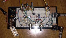
20221012_182221.jpg

Plugged everything and had nothing but noise, just to notice I had left the gate of the first jfet disconnected.
With everything properly connected, it works just fine, except that I had to use B1M for the drive pots (had to split the dual A1M), which makes it a bit hard to control.
Sounds pretty good, with loads of gain, but of course I won't claim it sounds like the preamp of the rockerverb.
I have yet to test it being hit with dirt pedals. Jfets used were some sk304 with measured vp around -0.9V and IDss around 0.9mA

I will test it a little more, but it seems destined to be properly built and boxed

Edit: I'm powering it with a 22v supply (the litlle veroboard)
 
First stage in a real amp usualy does not distort/clip the signal. It's highly possible that in your circuit there's already some distortion at Q1.
I'd suggest - replacing Q1 2SK304 with 2N5457 or 2N5458 or similar and removing 10u cap from Q1 drain. Or at least removing 10u.
 
First stage in a real amp usualy does not distort/clip the signal. It's highly possible that in your circuit there's already some distortion at Q1.
I'd suggest - replacing Q1 2SK304 with 2N5457 or 2N5458 or similar and removing 10u cap from Q1 drain. Or at least removing 10u.
Great! Thanks for the suggestion, I will try it later today.
Have you tried the schottky diode between gate and source that AMT uses in their preamp pedals? Do you think it is worth it?
 
Sometimes I use diodes (1N4148) between gate and gnd. Here I'd try to put one 1N4148 between Q2 gate and gnd and the same for Q4.
 
First stage in a real amp usualy does not distort/clip the signal. It's highly possible that in your circuit there's already some distortion at Q1.
I'd suggest - replacing Q1 2SK304 with 2N5457 or 2N5458 or similar and removing 10u cap from Q1 drain. Or at least removing 10u.
I tried your suggestion of removing the 10uF and it's an amazing difference! Gain pots have a much better range now and the note definition is much improved. I will try some 2sk246 in place of q1 and listen to it, but I already love the way it sounds. I have Eagle running as I type, because this is definetely getting a pcb design
Sometimes I use diodes (1N4148) between gate and gnd. Here I'd try to put one 1N4148 between Q2 gate and gnd and the same for Q4.
Nice! I will try them and see how they sound
 
You can also play with the gain of the second stage.
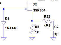
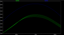
Try reducing 10u to 4.7u, 2u2 or even 1u. With 1u/2u2 it may be necessary to put a resistor in series with capacitor - in order to "restore" frequency response. For the simulation I've used following R25 values - 330R, 470R, 680R, 1k.

1665724300501.png


Frequency response of the second stage. Blue trace - tube, green traces - transistor. Top green trace = 330R for the R25.
1665724437048.png
 
You can also play with the gain of the second stage.
Try reducing 10u to 4.7u, 2u2 or even 1u. With 1u/2u2 it may be necessary to put a resistor in series with capacitor - in order to "restore" frequency response. For the simulation I've used following R25 values - 330R, 470R, 680R, 1k.

View attachment 33883


Frequency response of the second stage. Blue trace - tube, green traces - transistor. Top green trace = 330R for the R25.
View attachment 33884
That's amazing! Do you have a spice model for the 2sk304? If so, would you be willing to share it?
 
I've found this model somewhere in the net so cannot be sure about it's accuracy.

.model 2SK304 NJF (Beta=3.7m Rs=22.22 Rd=22.22 Betatce=-.5 Lambda=7.407m Vto=-1.728 Vtotc=-2.5m Cgd=3.336p M=.3333 Pb=1 Fc=.5 Cgs=3.5p Isr=174.9p Nr=2 Is=17.49p N=1 Xti=3 Alpha=10u Vk=100 Kf=1E-18 Af=1)

Vp of the above model is much higher than yours. -1.728V vs -0.9V. So here's the question - measurement error or wide spread of the parameters for different batches? For my simulation I lowered Vp in the model to -0.9V (Vto parameter) and also decreased Beta to match Idss.

My model
.model 2SK304 NJF (Beta=1.1m Rs=22.22 Rd=22.22 Betatce=-.5 Lambda=7.407m Vto=-0.9 Vtotc=-2.5m Cgd=3.336p M=.3333 Pb=1 Fc=.5 Cgs=3.5p Isr=174.9p Nr=2 Is=17.49p N=1 Xti=3 Alpha=10u Vk=100 Kf=1E-18 Af=1)
 
Awesome, Temol, thanks a lot!
In the datasheet, values of -Vgs(off) range from typical=1V to max=4V, with no mention of minimum values. So I guess both 0.9V and 1.728V are reasonable.
Idss also varies largely: the ones I have range from 0.6 to 1.5mA (C-type), but the 2SK304 in general ranges from 0.6 to 12 mA (all this according to the datasheet)
 
So, after further testing, I've added the diodes before Q2 and Q4. I'll probably keep'em, or at least make them switchable.

I've tried your suggestions on the 2nd stage and decided to remove the cap altogether
Finally, I've decided to use a 1k in series with a 1uf cap in the 3rd stage, in place of the 10u. There's probably less gain now than a rockerverb, but I prefer it this way, much better gain range for my needs.

I don't love the idea of having the output straight after the tonestack, so I'm pondering adding either a buffer or a differential stage that could even bring some distortion characteristics of the phase inverter (was thinking of chuck's fet tube bender)

Samples will be recorded after it's boxed, and preferrably not at my place, as I seem to live on top of a freaking antenna
 
Buffer or another gain stage - you have to test it on a breadboard. With your ears.
I'd go for a buffer, especially that you've just cut the overall gain down.
 
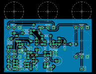
Board is designed:
board.png
It could be made smaller, but I have a 1590bb waiting to be used.
I don't have much experience designing boards for high(ish) gain stuff. Any obvious non-desirable practice?
I will use shielded wires and board mouted pots
I have decided not to use the buffer for now, might add as a switchable daughter board later
schematic.png
Edit: I never know if the ground plane should encircle the whole board, what is your general opinion on the matter?
 
I think that 100u for the supply caps is enough. Also - if you take look at tube amps schematics, the input section usually has the best supply filtering in the entire circuit (especially in hi-gain amps). Therefore, you could swap VA and VB in places.
 
I think that 100u for the supply caps is enough. Also - if you take look at tube amps schematics, the input section usually has the best supply filtering in the entire circuit (especially in hi-gain amps). Therefore, you could swap VA and VB in places.
Nice, will do that! Thanks!
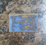
Will double check and etch tomorrow
 
I just started learning to make boards with Eagle, but I've been trying to make sure the ground plane goes around the whole board with no big voids around the parts anywhere. Did you not want to put trimmers on the Jfets to make sure you can dial in the proper bias?
 
I just started learning to make boards with Eagle, but I've been trying to make sure the ground plane goes around the whole board with no big voids around the parts anywhere.
I tend to take the same approach regarding the ground plane, but I've read somewhere that it could cause ground loops sometimes...
Did you not want to put trimmers on the Jfets to make sure you can dial in the proper bias?
I've biased the jfets on my breadboard. Q1, Q3 and Q4 are actually pretty matched, that's why the drain resistors have the same value, and as I'm taking it from breadboard to pcb, I've decided not to use trimpots and save some space and hopefully reduce noise (once again, read in a few different somewheres, but some of them are quite knowledgeable)
 
Back
Top