SMD Electrolytic Capacitor Hack

Cybercow

Well-known member
Many of us have been there. PCB is freshly populated, tested and working great. Now it's time to stuff all that goodness into a prepped enclosure. The drill holes have all been made and pre-fit tested for proper alignment and the guts go in nicely and even the jacks are spot-on with no interferences. Great! But then you go to screw that bottom plate on, only to find a few of the caps are too tall for the bottom plate to rest flat for closure.

Sometimes we can go back in and lay some of those tall caps on their side, or perhaps there is room on the solder-side of the PCB the jockey those tall caps around. And sometimes none of those approaches work. It all depends on the build, the enclosure and the planning in its entirety.

That damned Z-axis! How many times do we overlook the z-axis when planning a build for enclosure fitting? I know I have, and too many times. Sometimes I had to re-order a deeper enclosure, say a 1590N or 125B for the 1590B, or a 125BB for the 1590BB that are shallower.

One day, on whim, I though to order a few different SMD electrolytic caps just see if those could be used. I just ordered a generic SMD electrolytic capacitor kit and when they arrived I noticed they have this small plastic shroud on the bottom. At first I thought: "Bummer!" Then I thought maybe that plastic bottom shroud would come off easily and the flat pins could be straightened to be like regular TTH caps.

The first thing I found out is that those legs on SMD electrolytic caps are aluminum, thin and fragile. Bend 'em too many times and the metal fatigue gets the better of them and they break. So, with a delicate hand I carefully removed the plastic shroud, gently straightened the pins - being careful to bend slowly and only as much as needed. The I set the shroudless SMD electrolytic cap into the holes for the 100µF on the PCB. The SMD legs are perfectly spaced for most electrolytic hole spacing and lo & behold, there is even enough of the SMD legs sticking thru the PCB to bend a bit to hold 'em in place while the PCB is upside-down and ready for soldering. The solder took and the joints looked good. Voila! A solution for large electrolytic caps without resorting to tantalums or searching forever thru complicated search engines to find the right, or even just shorter, electrolytic caps.

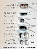
Here is a photo I took of a few different 100µF TTH e-Caps and two different SMD e-Caps with their respective specs and measurements. Over the past year or so, I would try different sizes of standard TTH e-Caps available from Mouser just to have some physically on hand to work with and see how well would or would not work in my pedals. It's difficult to source small TTH e-Caps of any real quality, especially for the larger values like 47µF and 100µF. Sometimes they are too tall, or when a shorter one is found, its width is too wide to fit easily next to components around it. The SMD versions will almost always work. Again, depending on the build. YMMV
100uF_e-Caps.jpg

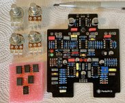
I built out 20 of the PedalPCB "Proposition" boards using SMD e-Caps, except for the 1µF e-Cap which was small enough on its own. They fit quite nicely into a 1590BB enclosure with height issues.
Proposition_PCB_00.jpg

In summary, for me at least, I find using SMD e-Caps a great alternative for larger TTH e-Caps. SMD e-Cap kits are cheap - about 20 bux for an assortment with 400 caps ranging from 1µF @ 10V to 1000µF @ 16V with higher voltage specs on the 330µF and below. For me, the 100µF @ 35V is the winner for most every need for a 100µF e-Cap.
 
Last edited:
Many of us have been there. PCB is freshly populated, tested and working great. Now it's time to stuff all that goodness into a prepped enclosure. The drill holes have all been made and pre-fit tested for proper alignment and the guts go in nicely and even the jacks are spot-on with no interferences. Great! But then you go to screw that bottom plate on, only to find a few of the caps are too tall for the bottom plate to rest flat for closure.

Sometimes we can go back in and lay some of those tall caps on their side, or perhaps there is room on the solder-side of the PCB the jockey those tall caps around. And sometimes none of those approaches work. It all depends on the build, the enclosure and the planning in its entirety.

That damned Z-axis! How many times do we overlook the z-axis when planning a build for enclosure fitting? I know I have, and too many times. Sometimes I had to re-order a deeper enclosure, say a 1590N or 125B for the 1590B, or a 125BB for the 1590BB that are shallower.

One day, on whim, I though to order a few different SMD electrolytic caps just see if those could be used. I just ordered a generic SMD electrolytic capacitor kit and when they arrived I noticed they have this small plastic shroud on the bottom. At first I thought: "Bummer!" Then I thought maybe that plastic bottom shroud would come off easily and the flat pins could be straightened to be like regular TTH caps.

The first thing I found out is that those legs on SMD electrolytic caps are aluminum, thin and fragile. Bend 'em too many time and the metal fatigue gets the better of them and they break. So, with a delicate hand I carefully removed the plastic shroud, gently straightened the pins - being careful to bend slowly and only as much as needed. The I set the shroudless SMD electrolytic cap into the holes for the 100µF on the PCB. The SMD legs are perfectly spaced for most electrolytic hole spacing and lo & behold, there is even enough of the SMD legs sticking thru the PCB to bend a bit to hold 'em in place while the PCB is upside-down and ready for soldering. The solder took and the joints looked good. Voila! A solution for large electrolytic caps without resorting to tantalums or searching forever thru complicated search engines to find the right, or even just shorter, electrolytic caps.

Here is a photo I took of a few different 100µF TTH e-Caps and two different SMD e-Caps with their respective specs and measurements. Over the past year or so, I would try different sizes of standard TTH e-Caps available from Mouser just to have some physically on hand to work with and see how well would or would not work in my pedals. It's difficult to source small TTH e-Caps of any real quality, especially for the larger values like 47µF and 100µF. Sometimes they are too tall, or when a shorter one is found, its width is too wide to fit easily next to components around it. The SMD versions will almost always work. Again, depending on the build. YMMV

View attachment 46023

I built out 20 of the PedalPCB "Proposition" boards using SMD e-Caps, except for the 1µF e-Cap which was small enough on its own. They fit quite nicely into a 1590BB enclosure with height issues.
View attachment 46024

In summary, for me at least, I find using SMD e-Caps a great alternative for larger TTH e-Caps. SMD e-Cap kits are cheap - about 20 bux for an assortment with 400 caps ranging from 1µF @ 10V to 1000µF @ 16V with higher voltage specs on the 330µF and below. For me, the 100µF @ 35V is the winner for most every need for a 100µF e-Cap.
Do they come in different Colours? ;)
 
do people often need an ecap greater than 25V?
It depends on the circuit. In some genuine vacuum tube pedals, the voltages can be higher than the standard 9V. The rule of thumb I learned was to rate an e-Cap at least1.5x the rated circuit voltage. E-Caps have their life span rated in hours, typically 1,000/2,000/3,000 and sometimes as high as 5,000 hours. That rated life span is determined at near ax heat limits for the specific cap. So a 25V e-Cap rated with a 2,000 hour anticipated life span can easily last for years of use when subjected to only 9v and negligible heat. Milage will vary depending on the heat the cap is exposed to, voltage spikes and reverse polarity - it which case it might even explode.
 
Going by the rule of 2x supply voltage, 18v pedals should have 36v or higher.
There are also some DEFX projects that take 24VDC
IMO & IME: The "2x supply voltage rule" is optional. From what I learned in Color TV Electronics, running e-Caps at about 80% (~1.2x rule) of their voltage ratings is adequate. 1.5x is the rule I use. The 2x rule is not necessary, but certainly will not hurt. Even a 5x rule (for voltage) is fine - but then device dimensions become an issue.
 
Many of us have been there. PCB is freshly populated, tested and working great. Now it's time to stuff all that goodness into a prepped enclosure. The drill holes have all been made and pre-fit tested for proper alignment and the guts go in nicely and even the jacks are spot-on with no interferences. Great! But then you go to screw that bottom plate on, only to find a few of the caps are too tall for the bottom plate to rest flat for closure.

Sometimes we can go back in and lay some of those tall caps on their side, or perhaps there is room on the solder-side of the PCB the jockey those tall caps around. And sometimes none of those approaches work. It all depends on the build, the enclosure and the planning in its entirety.

That damned Z-axis! How many times do we overlook the z-axis when planning a build for enclosure fitting? I know I have, and too many times. Sometimes I had to re-order a deeper enclosure, say a 1590N or 125B for the 1590B, or a 125BB for the 1590BB that are shallower.

One day, on whim, I though to order a few different SMD electrolytic caps just see if those could be used. I just ordered a generic SMD electrolytic capacitor kit and when they arrived I noticed they have this small plastic shroud on the bottom. At first I thought: "Bummer!" Then I thought maybe that plastic bottom shroud would come off easily and the flat pins could be straightened to be like regular TTH caps.

The first thing I found out is that those legs on SMD electrolytic caps are aluminum, thin and fragile. Bend 'em too many time and the metal fatigue gets the better of them and they break. So, with a delicate hand I carefully removed the plastic shroud, gently straightened the pins - being careful to bend slowly and only as much as needed. The I set the shroudless SMD electrolytic cap into the holes for the 100µF on the PCB. The SMD legs are perfectly spaced for most electrolytic hole spacing and lo & behold, there is even enough of the SMD legs sticking thru the PCB to bend a bit to hold 'em in place while the PCB is upside-down and ready for soldering. The solder took and the joints looked good. Voila! A solution for large electrolytic caps without resorting to tantalums or searching forever thru complicated search engines to find the right, or even just shorter, electrolytic caps.

Here is a photo I took of a few different 100µF TTH e-Caps and two different SMD e-Caps with their respective specs and measurements. Over the past year or so, I would try different sizes of standard TTH e-Caps available from Mouser just to have some physically on hand to work with and see how well would or would not work in my pedals. It's difficult to source small TTH e-Caps of any real quality, especially for the larger values like 47µF and 100µF. Sometimes they are too tall, or when a shorter one is found, its width is too wide to fit easily next to components around it. The SMD versions will almost always work. Again, depending on the build. YMMV

View attachment 46023

I built out 20 of the PedalPCB "Proposition" boards using SMD e-Caps, except for the 1µF e-Cap which was small enough on its own. They fit quite nicely into a 1590BB enclosure with height issues.
View attachment 46024

In summary, for me at least, I find using SMD e-Caps a great alternative for larger TTH e-Caps. SMD e-Cap kits are cheap - about 20 bux for an assortment with 400 caps ranging from 1µF @ 10V to 1000µF @ 16V with higher voltage specs on the 330µF and below. For me, the 100µF @ 35V is the winner for most every need for a 100µF e-Cap.
What "kit" did you get?
 
Can only echo the thoughts of others. This is game changing. I can't think of anything more impactful to the build process.
Thanks a lot for sharing!

Next, I'll learn that you can just solder 0805 e-caps straight across the pads..
 
Thanks for this game-changer, @Cybercow, twill really help those stacked board builds, 1590A etc.

I, like iamjackslackof, try to power things up for more headroom, in general, but particularly works well for bass.


@music6000 I know where you can get coloured caps...

💅


Custom colours, prints, motifs from marble to murals...

18a81d6609c7fa084491a574702b530a.jpg

631a47975bcc4a7690ce840185befaf4.jpg


535080705d49df68fb08ec3713ed0679.jpg
 
Many of us have been there. PCB is freshly populated, tested and working great. Now it's time to stuff all that goodness into a prepped enclosure. The drill holes have all been made and pre-fit tested for proper alignment and the guts go in nicely and even the jacks are spot-on with no interferences. Great! But then you go to screw that bottom plate on, only to find a few of the caps are too tall for the bottom plate to rest flat for closure.

Sometimes we can go back in and lay some of those tall caps on their side, or perhaps there is room on the solder-side of the PCB the jockey those tall caps around. And sometimes none of those approaches work. It all depends on the build, the enclosure and the planning in its entirety.

That damned Z-axis! How many times do we overlook the z-axis when planning a build for enclosure fitting? I know I have, and too many times. Sometimes I had to re-order a deeper enclosure, say a 1590N or 125B for the 1590B, or a 125BB for the 1590BB that are shallower.

One day, on whim, I though to order a few different SMD electrolytic caps just see if those could be used. I just ordered a generic SMD electrolytic capacitor kit and when they arrived I noticed they have this small plastic shroud on the bottom. At first I thought: "Bummer!" Then I thought maybe that plastic bottom shroud would come off easily and the flat pins could be straightened to be like regular TTH caps.

The first thing I found out is that those legs on SMD electrolytic caps are aluminum, thin and fragile. Bend 'em too many time and the metal fatigue gets the better of them and they break. So, with a delicate hand I carefully removed the plastic shroud, gently straightened the pins - being careful to bend slowly and only as much as needed. The I set the shroudless SMD electrolytic cap into the holes for the 100µF on the PCB. The SMD legs are perfectly spaced for most electrolytic hole spacing and lo & behold, there is even enough of the SMD legs sticking thru the PCB to bend a bit to hold 'em in place while the PCB is upside-down and ready for soldering. The solder took and the joints looked good. Voila! A solution for large electrolytic caps without resorting to tantalums or searching forever thru complicated search engines to find the right, or even just shorter, electrolytic caps.

Here is a photo I took of a few different 100µF TTH e-Caps and two different SMD e-Caps with their respective specs and measurements. Over the past year or so, I would try different sizes of standard TTH e-Caps available from Mouser just to have some physically on hand to work with and see how well would or would not work in my pedals. It's difficult to source small TTH e-Caps of any real quality, especially for the larger values like 47µF and 100µF. Sometimes they are too tall, or when a shorter one is found, its width is too wide to fit easily next to components around it. The SMD versions will almost always work. Again, depending on the build. YMMV

View attachment 46023

I built out 20 of the PedalPCB "Proposition" boards using SMD e-Caps, except for the 1µF e-Cap which was small enough on its own. They fit quite nicely into a 1590BB enclosure with height issues.
View attachment 46024

In summary, for me at least, I find using SMD e-Caps a great alternative for larger TTH e-Caps. SMD e-Cap kits are cheap - about 20 bux for an assortment with 400 caps ranging from 1µF @ 10V to 1000µF @ 16V with higher voltage specs on the 330µF and below. For me, the 100µF @ 35V is the winner for most every need for a 100µF e-Cap.
Saving this. This is crazy good info! Thanks!
Did you have any with the aluminum leads taking solder easily?
Did you have to crank up the temp on the iron?

Was it relatively easy to pry the plastic shroud off?
 
Last edited:
Back
Top