You are using an out of date browser. It may not display this or other websites correctly.
You should upgrade or use an alternative browser.
You should upgrade or use an alternative browser.
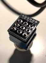
Soldered 3PDT Breakout Board Upside-down
- Thread starter joelorigo
- Start date
Mcknib
Well-known member
Should be fine doesn't matter if it's flipped
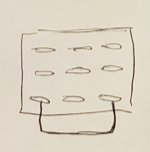
As long as you place your 2 jumpered lugs at the bottom (bypass)
Easy enough to check your bypass row is at the bottom, just continuity check the bottom row has the 2 outer lugs connected

Where did you get it is it a ppcb board if so just wire it as normal
It doesn't matter if it says out on the left now etc it's just labelling as long as you wire your IN and OUT jack and pcb in and out to the correct side and you've got your jumpered lugs at the bottom all will be good
As long as you place your 2 jumpered lugs at the bottom (bypass)
Easy enough to check your bypass row is at the bottom, just continuity check the bottom row has the 2 outer lugs connected

Where did you get it is it a ppcb board if so just wire it as normal
It doesn't matter if it says out on the left now etc it's just labelling as long as you wire your IN and OUT jack and pcb in and out to the correct side and you've got your jumpered lugs at the bottom all will be good
Last edited:
guitarfreak2105
New member
Desolder wick works very well for this application. Better to do it right than to Jerry rig it and have issues.
When I first started soldering I was also horrible at desoldering even with wick. A couple of tips 1) use relatively thin desolder wick for these small parts. Too thick and it could not heat up enough to work efficiently. 2) use a high-quality iron that gets hot enough (I find 750° works well) 3) Some of those switches and other components can be sensitive. Try not to heat them up for more than 3-5 seconds at a time. Work fast. Even more reason to be using a good iron and the right tip for the job.
Good luck.
joelorigo
Well-known member
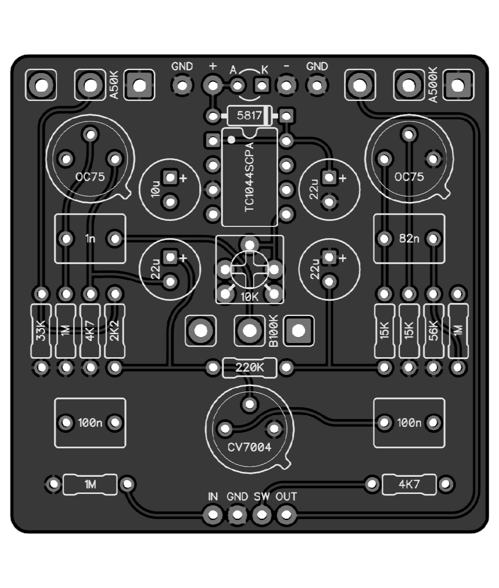
Actually I did this a few months ago. I had more breakout boards and foot switches so I just put this aside and used other ones. I found this in my box of parts because I am now building a Betty Boost. I have no plans at the moment for any builds but was hoping I could still use the switch in the future.
Mcknib
Well-known member
Should be fine with a betty boostActually I did this a few months ago. I had more breakout boards and foot switches so I just put this aside and used other ones. I found this in my box of parts because I am now building a Betty Boost. I have no plans at the moment for any builds but was hoping I could still use the switch in the future.
The output grounded in bypass won't cause any problem as you know that vertical links just there to help with switch pop so there's a small chance you may get a pop but you've got the 1M at the input so should be ok
Tbh although it's good practice I never usually ground the input and I have on occasion accidentally grounded the output when distracted by somebody shouting chocolate! and never had a problem
Last edited:
turntablemonkey
New member
Ok so I had a similar experience with the daughterboard from the paragon build. Soldered it in upside down. So I wired it up with wires but the switch was turning on the opposite side of the effect. I had accidentally wired it backwards. Ordered another paragon pcb aaaaand I did it again. Luckily I had only soldered a few lugs before I realized my mistake. Was able to use a solder sucker to remove the majority of the solder and then heating random lugs while wiggling the switches and I was home free.
joelorigo
Well-known member
What about the Blender project? I've been interested in this one for a while.
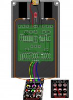
Could I use my mistake switch & board assembly as shown in the in the diagram? Or should I reverse the wiring?
Could I use my mistake switch & board assembly as shown in the in the diagram? Or should I reverse the wiring?
joelorigo
Well-known member
Instead of the Blender I ordered the Kilimanjaro Fuzz PCB.
Can I use the switch & board assembly as mistakenly assembled? Or should I reverse the wiring?

Can I use the switch & board assembly as mistakenly assembled? Or should I reverse the wiring?

Mcknib
Well-known member
If you haven't already check the switch isn't heat damaged first
The only difference is your diagonal link is on the output side so output would be grounded in bypass mode instead of the input and I think your SW and GND would be flipped but you could continuity check to make sure check the coloured dots on the 3PDT board have continuity with their corresponding 3PDT lugs and the red links connect if they do wire it as shown below
Regardless of which way round you've soldered it to the board the actual switch still works the same way, as you know the in and out jacks are connected to the middle common row switched or thrown to the top row connects the in jack to the circuit input through the circuit to the output pad to the out jack also connecting your LED to ground turning it on, switched the other way middle common row connects to the bottom row your in jack connecting to jumpered lug along the jumper to the out jack bypassing the circuit at the same time disconnecting the LED ground and switching it off so the PCB being flipped from that point of view doesn't matter the middle row would still connect to the top or bottom row
You can reference the 3PDT board the right way round flip it and you'll see what I mean, using pictures always makes it easier for me!

Similar threads
- Replies
- 2
- Views
- 223
- Replies
- 5
- Views
- 459
- Replies
- 0
- Views
- 299
- Replies
- 5
- Views
- 528
- Replies
- 1
- Views
- 208


