[Solved] Cepheid Chorus - only the LEDs work

zipfool

Member
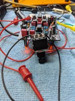
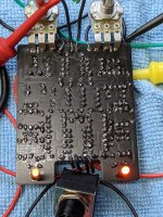
This seems like it's going to be tricky to figure out. Bypass works fine, but the 2nd LED stays lit even in bypass. When I engage the switch, both LEDs light up, but I'm not hearing any of the Chorus effect no matter how much I crank the knobs/pots.

I opted to go with the MN3207 / MN3102 IC pairing, but I suspect that my source for these was bogus (seller on EBay). I've tried 4 out of 10 of the pairs they sold me, and I'm getting the same [lack of] effect with all 4 pairs. I could keep trying out the other pairs, but I'm suspicious that all of them will be the same.

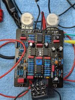
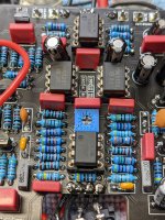
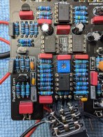
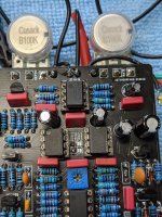
Take a look at these photos and LMK if you see anything else suspicious.

There's a few things to this build that are new to me: not sure what the trim pot is supposed to control, and I've never had to solder an onboard jumper to signify which chip combo I bought. Did I do the right thing by putting a bead of solder to connect each of the 2 sets of pads?

If I dial the trim pot up too high, the sound cuts out. Same if dial it too low. Right in the middle and I get clear sound/tone. What does this trim pot do?
 

Attachments

  • PXL_20210822_004202661_resize_50.jpg
    PXL_20210822_004202661_resize_50.jpg
    1.5 MB · Views: 71
  • PXL_20210822_004244821_resize_0.jpg
    PXL_20210822_004244821_resize_0.jpg
    1.5 MB · Views: 76
  • PXL_20210822_004257660_resize_7.jpg
    PXL_20210822_004257660_resize_7.jpg
    1.4 MB · Views: 81
  • PXL_20210822_004319321_resize_1.jpg
    PXL_20210822_004319321_resize_1.jpg
    1.5 MB · Views: 58
  • PXL_20210822_004328108_resize_1.jpg
    PXL_20210822_004328108_resize_1.jpg
    1.4 MB · Views: 56
  • PXL_20210822_004351851_resize_28.jpg
    PXL_20210822_004351851_resize_28.jpg
    1.7 MB · Views: 58
The trimpot controls the Vref value to dial in the sweet-spot for the chorus effect. Its a VERY narrow margin - usually just off center.

Also, did you use the 9.1v Zener diode for D101 withe MN32xx chipset? (If you have the higher value Zener and are using greater than 9v to supply the circuit - it might be problematic. The 9.1v Zener is to protect the MN32xx chipset. The MN30xx chipset can withstand a bit more voltage.)

I'd first ensure that no more than 9V is supplying the circuit, try a fresh set of the MN32xx chips, and try carefully adjusting the trimpot. Be sure to have the Depth pot turned up all the way and the Rate pot at the mid-point. See if adjusting the trimmer while playing an audio signal thru the circuit will dial-in. Use tiny increments.
 
Question: is your rate LED on 100% of the time, or does it cycle on and off with, blinking faster as you turn up the rate potentiometer?

If it's not cycling on and off, there's a good chance that you'll need to poke around the LFO portion of the circuit, as illustrated here:

Screenshot_20210822-110442__01.jpg
 
The plot thickens, but maybe this makes it more obvious what's going wrong ...

I see now that the LEDs only light up when I've got the ground and hot wires mixed up on the dc jack. When I have the jack wired properly, I get no LEDs or sound when the footswitch is engaged. Bypass still works fine.
 
This is a shot in the dark for me, but I just wanted to ask to be sure: you replaced C20 with a polarized cap - are you sure it's aligned in the correct polarity? I took a look at the schematic, but can't tell how it needs to be aligned on the board since I can't see the traces on the PCB. Just thought I'd ask!
 
Oooo.

Check your LED orientation. Anode to A and Cathode to K? During the initial build, you would want to put the long leg of the LED through the round pad.

It looks like you have C-20 oriented correctly (negative towards output)...double check the LEDs first, there may also be something else going on in the circuit.

IC voltages could help here.
 
You could have quite a few cold joints there as well. It’s definitely worth reflowing (with the ICs removed) and then clean the board with IPA to rule that out.
 
This is a shot in the dark for me, but I just wanted to ask to be sure: you replaced C20 with a polarized cap - are you sure it's aligned in the correct polarity? I took a look at the schematic, but can't tell how it needs to be aligned on the board since I can't see the traces on the PCB. Just thought I'd ask!
That's an interesting question. C20 *is* supposed to be a film capacitor. Would that cause the pedal to malfunction? I could always flip the polarity, but Stickman393 is saying I've got it right. I might just order a 1uf film capacitor if that might make all the difference...
 
That's an interesting question. C20 *is* supposed to be a film capacitor. Would that cause the pedal to malfunction? I could always flip the polarity, but Stickman393 is saying I've got it right. I might just order a 1uf film capacitor if that might make all the difference...
If that cap is in the correct way the. Changing it to film won’t make a difference unfortunately. Where do you get your MN3207?
 
Oooo.

Check your LED orientation. Anode to A and Cathode to K? During the initial build, you would want to put the long leg of the LED through the round pad.

It looks like you have C-20 oriented correctly (negative towards output)...double check the LEDs first, there may also be something else going on in the circuit.

IC voltages could help here.
I just checked the LEDs and they're oriented correctly. That for the suggestion though.

Here are the IC voltages:

TL022cp:
-.008
-.008
-.008
0
-.008
-.007
-.008
-.016

MN3207
0
.028
0
-.015
-.016
.025
0
0

MN3102
-.016
.029
0
.032
-.62
0
-.015
-.015

TL072CP (same readings if I use RC4558)
-.008
-.008
-.008
0
-.008
-.007
-.007
-.017
 
Last edited:
Bah, nevermind everyone. I'm completely missing C3 (100nf). I'm going to get my brain examined because this is some really basic shit :)

Ahhh, I see it. Can really only tell from the bottom.

Yup, that'll stop your LFO cold.

Those IC voltages don't look right...how are you taking those measurements?
 
So I soldered in the missing and wrong components, but I'm still getting the same voltages on ICs (with only two exceptions). I edited/corrected the values in the list I posted above.

Anyone know what would cause almost all of these values to be so low/negative voltages? I can't imagine that's normal for a circuit like this...
 
Anyone know what would cause almost all of these values to be so low/negative voltages? I can't imagine that's normal for a circuit like this...

The most likely cause is an incorrectly wired DC jack. What voltages do you read on each end of the 1N5817 diode at the top of the board?
 
Back
Top