
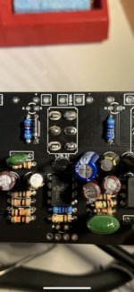
I screwed up and soldered the first dpdt switch of the three effects (centre chorus on/off switch) on the wrong side of the board. I was able to remove it and reinstall but pulled off a few pads in the process.
So I’m going to need to bridge some connections from components before, to and after the lugs of the dpdt switch.
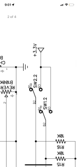
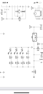
Looking at the schematic I am assuming the centre chorus switch is the “SW2”? Does anyone know how the A1, A2, A3 and B1, B2 and B3 on the schematic relates to the lugs on the switch? Or can help me figure out where the lugs go? This is a bit confusing for me to figure out and I don’t want to trash this board, specially as I’ve already soldered the fv-1 chip on it. Thanks!
So I’m going to need to bridge some connections from components before, to and after the lugs of the dpdt switch.
Looking at the schematic I am assuming the centre chorus switch is the “SW2”? Does anyone know how the A1, A2, A3 and B1, B2 and B3 on the schematic relates to the lugs on the switch? Or can help me figure out where the lugs go? This is a bit confusing for me to figure out and I don’t want to trash this board, specially as I’ve already soldered the fv-1 chip on it. Thanks!
Attachments
Last edited:
