SOLVED Son of Ben - Solder Pad Came Off

apierz

Member
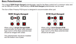
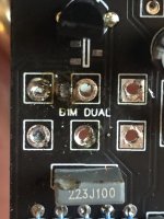
Problem: A solder pad on the Son of Ben PCB came off while installing components. The PCB requires a conducting bridge between the two solder pads when using a single gang potentiometer in the bass pot position.

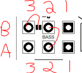
Solution: Bridge the two component holes as shown in the picture below by soldering a piece component lead or wire into the holes. Credit to @music6000 and @giovanni

pad-jumper-jpg.23685

Original Post:
----------------------
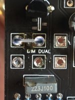
I am working on a Son of Ben. I have most of it soldered but was waiting on a B2M pot (I wasn't able to find a dual gang B1M). I had a very hard time trying to solder the bridge as required for using the B2M and when I finally got it some on and tried to trim it a little one of the solder pads of the bridge came off along with all the solder. Is there a way to fix this or have I ruined the PCB? IMG_2344.jpg
 
Last edited:
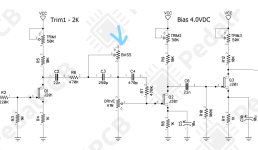
InkedCapture_LI.jpg Here's the spot on the schematic showing the Bass potentiometer that I think the solder bridge effects. I don't see anything on here indicating where that solder bridge is located in the circuit but I am a novice at this. I was able to find some dual gang B1M pots so if I am unable to fix it for use with the B2M single-gang I think I will still be able to use the B1M since that doesn't need the solder pads bridged. Capture1.PNG
 
Your board is 100% ok. Here is what I would do. Clean out the pads needed for the B2M with a solder sucker. Use a little piece of clipped lead from a resistor to make your connection by sticking both ends in the holes and solder as you normally would any component.
 
I would test for continuity between the pot pads and the rest of the circuit before proceeding with any other soldering.

In case it helps, when using the dual gang, the board is most likely designed to have the two sides of the two pots in series so you effectively get twice the resistance (which is what you want since we need 2M total). When using the single gang the connection must be rewired by bridging lug 2 of one gang to lug 1 of the other or alternatively lug 1 of one to lug 1 of the other (which is what those pads do). Which alternative is correct depends on how the dual gang pads are connected to the rest of the circuit, but you can expect one of those two options. @PedalPCB can confirm.

Also I would be more concerned about that melted capacitor…

Thank you! I thought the solder bridge must be mimicking the dual gang in this way. I don't know which of the two options it is but this narrows down the potential solutions.

Good spot on the melted capacitor, I will definitely replace it before trying to do anything with the pots.
 
I suspect your melted capacitor is just fine as is. Wait until you change the pot and see if everything is OK. then change the capacitor if needed. you might avoid a needless replacement, and at the very least putting the pot in first will stop you from melting a new capacitor if you replace it after the pot.
 
Capture2.PNG I tested the continuity with a multimeter. I got a beep between lugs 2A and 2B and between 3B and the remaining (left) solder pad. Does this help narrow down which holes to bridge?
 
I have this board and I can take a look with a multimeter tomorrow. If you want to resolve it sooner, go by the schematic: lug 1 of the 2M pot is supposed to be connected to lug 3 of the drive pot; lug 2 to R6 and C3. Check which pads connect to those. You will probably find that it’ll be one pad from gang A and one from gang B. If so, you just need to bridge whatever pad from the top row to the appropriate one on the bottom. If that’s not clear, you can report what connection you find or wait for me to check it out tomorrow. Sorry I couldn’t help more!
 
I have this board and I can take a look with a multimeter tomorrow. If you want to resolve it sooner, go by the schematic: lug 1 of the 2M pot is supposed to be connected to lug 3 of the drive pot; lug 2 to R6 and C3. Check which pads connect to those. You will probably find that it’ll be one pad from gang A and one from gang B. If so, you just need to bridge whatever pad from the top row to the appropriate one on the bottom. If that’s not clear, you can report what connection you find or wait for me to check it out tomorrow. Sorry I couldn’t help more!

This is all you need to do is pictured below as the B2M Legs only go in your A Position!:

View attachment 23685
Thank you both! That is very helpful. I will update the OP and mark this thread as Solved.
 
Back
Top